2 - 13
2 Specifications
NX-series Safety Control Unit User’s Manual (Z930)
2-2 Specifications of Individual Units
2
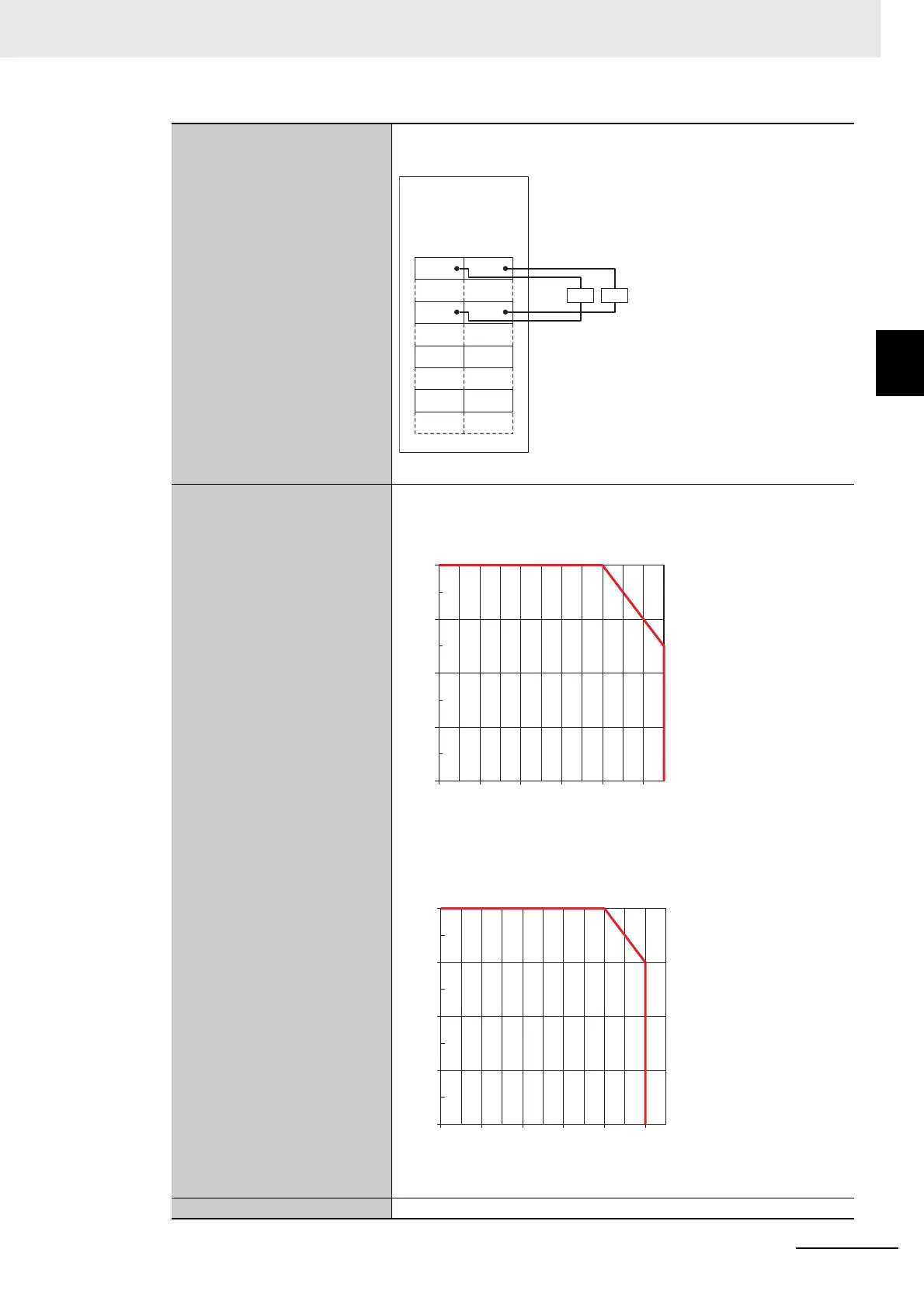
2-2-4 Safety Output Units
Terminal connection diagram
So0 and So1: Safety output terminals
IOG: I/O power supply 0 V
Refer to 3-3-2 Safety Output Functions on page 3-35 for details.
Installation orientation and
restrictions
Installation orientation: 6 possible orientations
Restrictions: For upright installation, the ambient temperature is restricted
as shown below according to the total Unit load current.
For all installation orientations other than upright installation, the ambient
temperature is restricted as shown below according to the total Unit load
current.
Protective functions Overvoltage protection circuit and short detection
NX-SOH200
Safety
Output Unit
So0
A1 B1
A8 B8
So1
LL
IOG IOG
NC NC
NC NC
Load current [A]
Ambient temperature [°C]
2
1
0
4
3
20 30 40 5550100
2.5 A
Load current [A]
Ambient temperature [°C]
2
1
0
4
3
20 30 40 50100