3 - 9
3 Part Names and Functions
NX-series Safety Control Unit User’s Manual (Z930)
3-2 Safety I/O Units
3
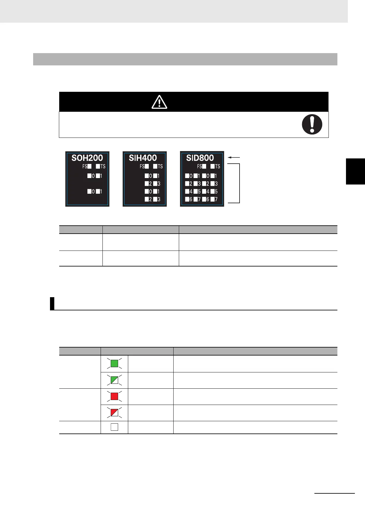
3-2-2 Indicators
A Safety I/O Unit has indicators that give the status of the Unit, communications, and the safety I/O ter-
minals.
The indicator pattern depends on the number of I/O points, as shown below.
The rest of this section gives the indicator specifications.
The TS indicator shows the current status of the Safety I/O Unit and the communications status with the
Communications Coupler Unit.
The following table lists the possible states for this indicator and what they mean.
3-2-2 Indicators
WARNING
Do not use the status of the indicators on the NX-series Safety Control Units for safety opera-
tions. This will compromise the safety functions of the Unit and may cause serious injury in the
event of an accident.
Letter Name Function
(A) Model number display Displays part of the model number of the Safety I/O Unit.
The model number indication is red on all Safety Control Units.
(B) Indicators Show the current operating status and communications status
of the Safety I/O Unit.
TS Indicator
Color Status Meaning
Green Lit. The Unit is operating normally.
The Unit is ready to refresh I/O.
Flashing at 2-s
intervals.
Initializing
Red Lit. A hardware error, WDT error, or other critical error has occurred.
Flashing at 1-s
intervals.
An NX bus communications error or other recoverable minor error
that is attributed to the NX bus has occurred.
--- Not lit. Power is not being supplied.
Unit with 8 I/O PointsUnit with 4 I/O PointsUnit with 2 I/O Points
(A)
(B)