3 Part Names and Functions
3 - 4
NX-series Safety Control Unit User’s Manual (Z930)
The FS indicator shows the safety communications status and safety function status of the Safety CPU
Unit.
The following table lists the possible states for this indicator and what they mean.
The RUN indicator shows the execution status of the safety programs.
The following table lists the possible states for this indicator and what they mean.
The DEBUG indicator shows the safety communications status and safety function status of the Safety
CPU Unit.
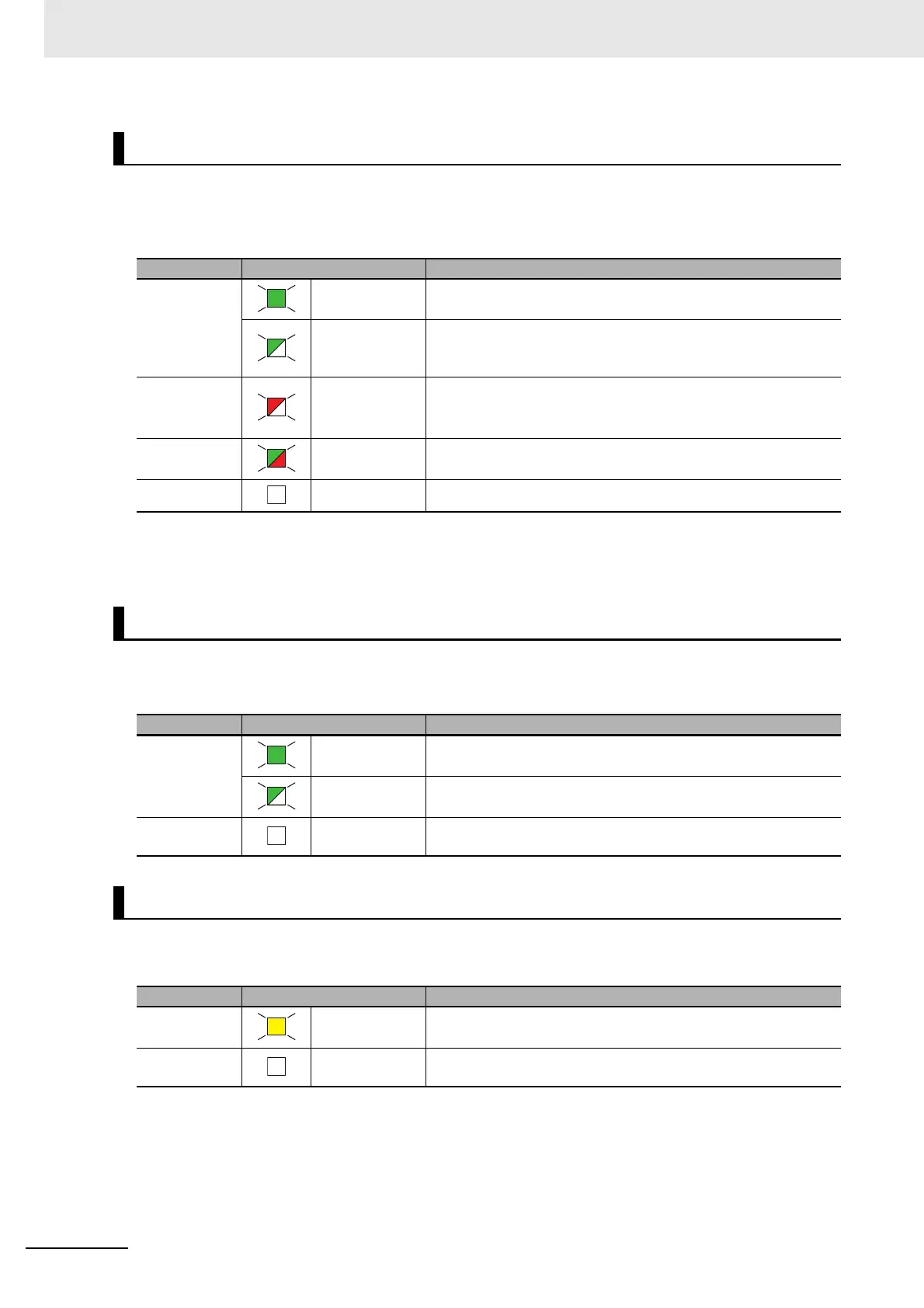
FS Indicator
Color Status Meaning
Green Lit. All FSoE connections are established and there are no errors in
any Safety CPU Unit functions.
Flashing at 1-s
intervals.
One or more FSoE connections are not established or are cur-
rently being established and there are no errors in any Safety
CPU Unit functions.
Red Flashing at 1-s
intervals.
An FSoE communications error, program execution error, or other
minor error that is attributed to the safety application has
occurred.
*1
*1. For approximately 30 seconds after the power supply to the Safety CPU Unit is turned ON, a Safety Process
Data Communications Initialization Error event is not registered as an error to indicate missing Safety I/O Units.
During that time, the FS indicator will flash green.
Green/Red Alternates at 1-s
intervals.
The safety application data has not been stored.
--- Not lit. Power is not being supplied or a fatal fault has occurred.
RUN Indicator
Color Status Meaning
Green Lit. Execution of a safety program is in progress (operation is in prog-
ress in RUN mode, or DEBUG mode (RUN)).
Flashing at 1-s
intervals.
Initialization is in progress (from when the power supply is turned
ON until RUN or PROGRAM mode is entered).
--- Not lit. Operation is in progress in PROGRAM mode or DEBUG mode
(STOPPED), or a fatal fault has occurred.
DEBUG Indicator
Color Status Meaning
Yellow Lit. Operation is in progress in DEBUG mode.
--- Not lit. Operation is in progress in a mode other than DEBUG mode or a
fatal fault has occurred.