4-19
4-2 Wiring
OMNUC G5-SERIES AC SERVOMOTOR AND SERVO DRIVE USER'S MANUAL
4
System Design
R88D-KT20H
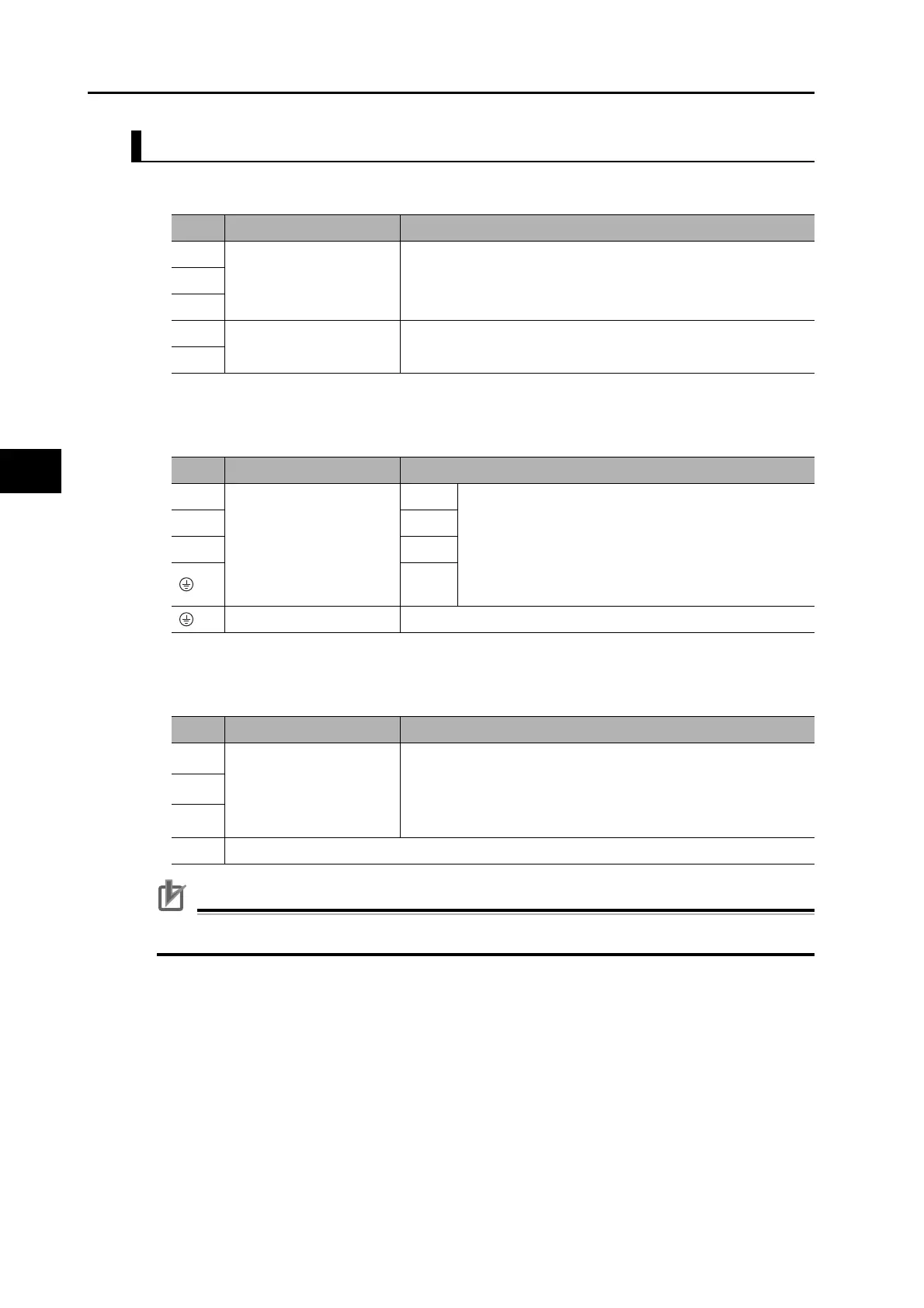
Main Circuit Connector Specifications (CNA)
Motor Connector Specifications (CNB)
External Regeneration Resistor Connector Specifications (CNC)
Precautions for Correct Use
Never connect an External Regeneration Resistor between the B1 and NC terminals.
Symbol
Name Function
L1 Main circuit power supply
input
R88D-KT@H (2 kW) :
3-phase: 200 to 230 VAC (170 to 253 V) 50/60 Hz
L2
L3
L1C Control circuit power
supply input
R88D-KT@H : Single-phase 200 to 230 VAC (170 to 253 V) 50/60
Hz
L2C
Symbol
Name Function
U Motor connection
terminals
Red These are the output terminals to the Servomotor.
Be sure to wire them correctly.
VWhite
WBlue
Green/
Yellow
Frame ground This is the ground terminal. Ground to 100 Ω or less.
Symbol
Name Function
B1
External Regeneration
Resistor connection
terminals
Normally B2 and B3 are shorted. Do not short B1 and B2. Doing
so may cause malfunctions.
If there is high regenerative energy, remove the short-circuit bar
between B2 and B3 and connect an External Regeneration
Resistor between B1 and B2.
B3
B2
NC Do not connect.
 Loading...


