4-42
4-3 Wiring Conforming to EMC Directives
OMNUC G5-SERIES AC SERVOMOTOR AND SERVO DRIVE USER'S MANUAL
4
System Design
Select a no-fuse breaker with a rated current greater than the total effective load current of all the
motors (when multiple Servo Drives are used). (The rated current of the power supply input for
each motor is provided in "Main Circuit and Motor Connections"(P.4-18).)
Add the current consumption of other controllers, and any other components when selecting.
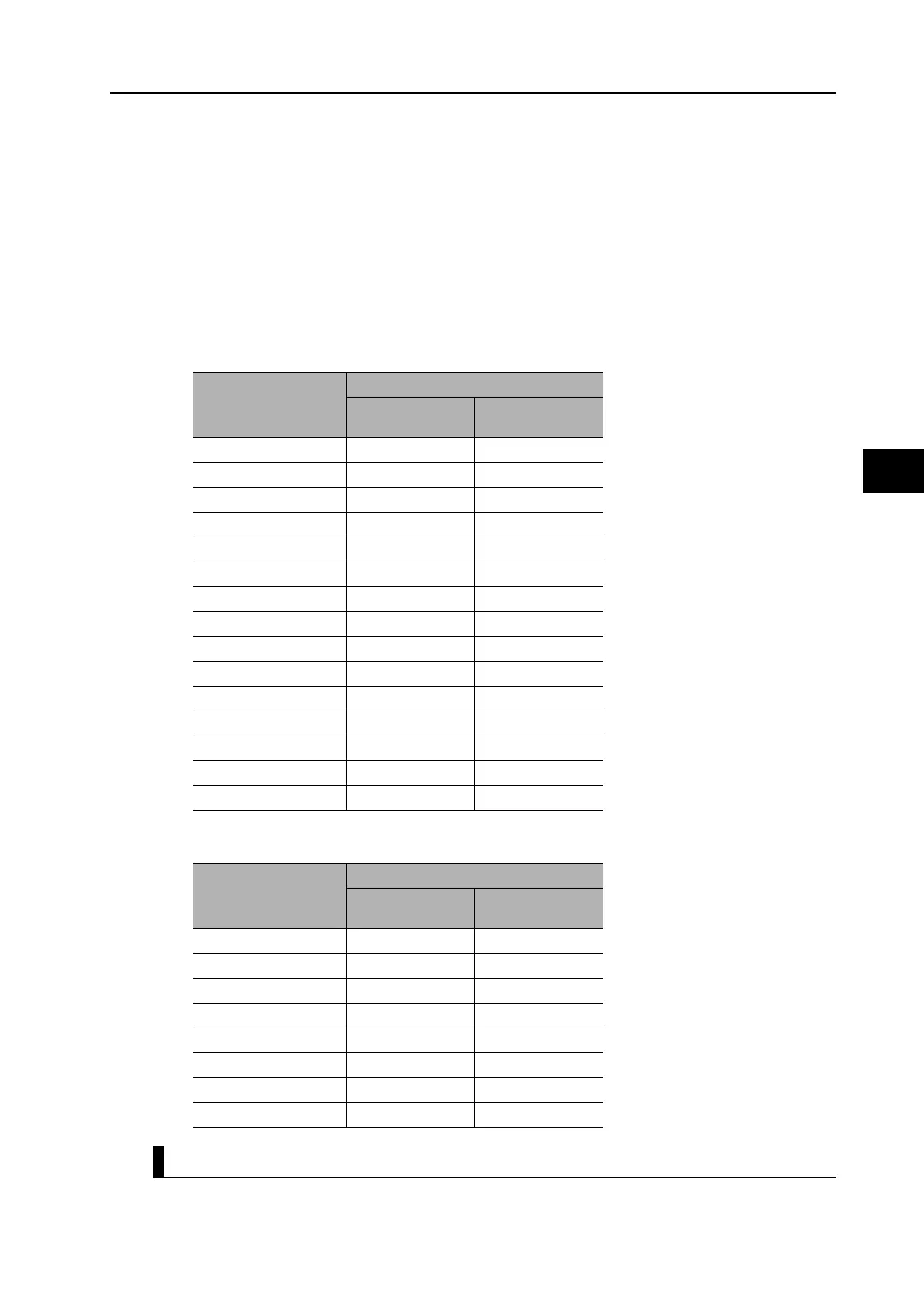
Inrush Current
The following table lists the Servo Drive inrush currents.
With low-speed no-fuse breakers, an inrush current 10 times the rated current can flow for 0.02
second.
When the power of multiple Servo Drives are turned ON simultaneously, select a no-fuse breaker
with a 20-ms allowable current that is greater than the total inrush current, shown in the following
table.
Leakage Breaker
Select a leakage breaker for high frequencies and surge resistance.
When selecting leakage breakers, remember to add the leakage current from devices other than
Servo Drive model
Inrush current (A0-p)
Main circuit power
supply
Control circuit
power supply
R88D-KTA5L 7 14
R88D-KT01L 7 14
R88D-KT02L 7 14
R88D-KT04L 15 14
R88D-KT01H 14 28
R88D-KT02H 14 28
R88D-KT04H 14 28
R88D-KT08H 29 28
R88D-KT10H 29 28
R88D-KT15H 29 28
R88D-KT20H 29 14
R88D-KT30H 22 14
R88D-KT50H 22 14
R88D-KT75H 66 15
R88D-KT150H 66 15
Servo Drive model
Inrush current (A0-p)
Main circuit power
supply
Control circuit
power supply
R88D-KT06F 28 48
R88D-KT10F 28 48
R88D-KT15F 28 48
R88D-KT20F 32 48
R88D-KT30F 32 48
R88D-KT50F 32 48
R88D-KT75F 32 48
R88D-KT150F 32 48
 Loading...


