12-4
12-1 Connection Examples
OMNUC G5-SERIES AC SERVOMOTOR AND SERVO DRIVE USER'S MANUAL
12
Appendix
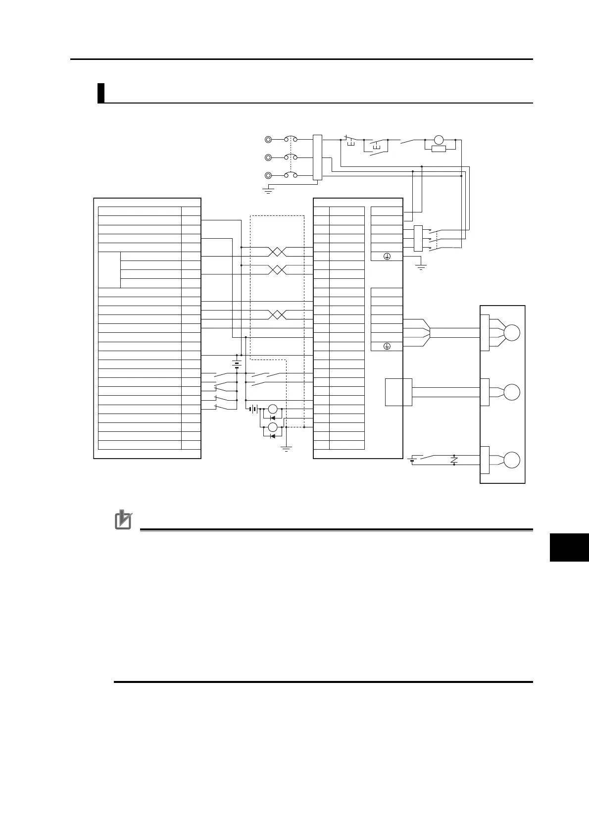
Connection Example 4: Connecting to SYSMAC CS1W-NC113/213/413 or C200HW-NC113/213/413
Precautions for Correct Use
The wiring for the pins with * is the same as it is when a Servo Relay Unit Cable is used. Set Pn005
(Command Pulse Input Selection) to 0 (photocoupler input).
The example shows a 3-phase, 200-VAC input to the drive for the main circuit power supply. Be
sure to provide a power supply and wiring conforming to the power supply specifications for the
drive in use.
Incorrect signal wiring can cause damage to units and the drive.
Leave unused signal lines open and do not wire them.
Use mode 2 for origin search.
The diode recommended for surge absorption is the RU 2 (Sanken Electric Co., Ltd.) or the
equivalent.
Make the setting so that the servo can be turned ON/OFF with the RUN signal.
CS1W-NC113/213/413
C200HW-NC113/213/413 R88D-KT@
No.
CN1 CNA
CNB
A1
A2
*6
*3
*4
30
23
24
39
7
29
31
38
36
Shell
*5 +CCW
L1C
L2C
L1
L2
L3
B1
B3
B2
U
V
W
−CCW
+CW
−CW
ECRST
+Z
INP
+24VIN
RUN
RESET
INPCOM
ALMCOM
FG
−Z
A8
A7
A6
A5
A16
A14
A12
A24
A19
A21
A23
A22
A20
24 VDC
X1
X1
24 VDC
XB
Description
24-V power supply for output
0-V power supply for output
X-axis origin common
X-axis positioning completed input
Input common
X-axis external interrupt input
X-axis origin proximity input
X-axis CCW limit input
X-axis CW limit input
X-axis immediate stop input
X-axis
pulse
output
X-axis error counter reset output
X-axis origin line-driver input
A10
BKIRCOM
10
BKIR
11
37 /ALM
M
Red
White
Blue
Green/Yellow
R88M-K
@
CN2
Motor power cables
E
24 VDC
Encoder cables
B
Brake cables
XB
R
S
T
1MC
NFB
Reactor
Noise filter
CCW (With resistance)
CCW (Without resistance)
CW (With resistance)
CW (Without resistance)
3-phase 200 to 240 VAC 50/60 Hz
Ground to
100 Ω or less
ONOFF
X
1MC
Main circuit power supply
Main circuit contactor
1MC
surge
suppressor
 Loading...


