12-6
12-1 Connection Examples
OMNUC G5-SERIES AC SERVOMOTOR AND SERVO DRIVE USER'S MANUAL
12
Appendix
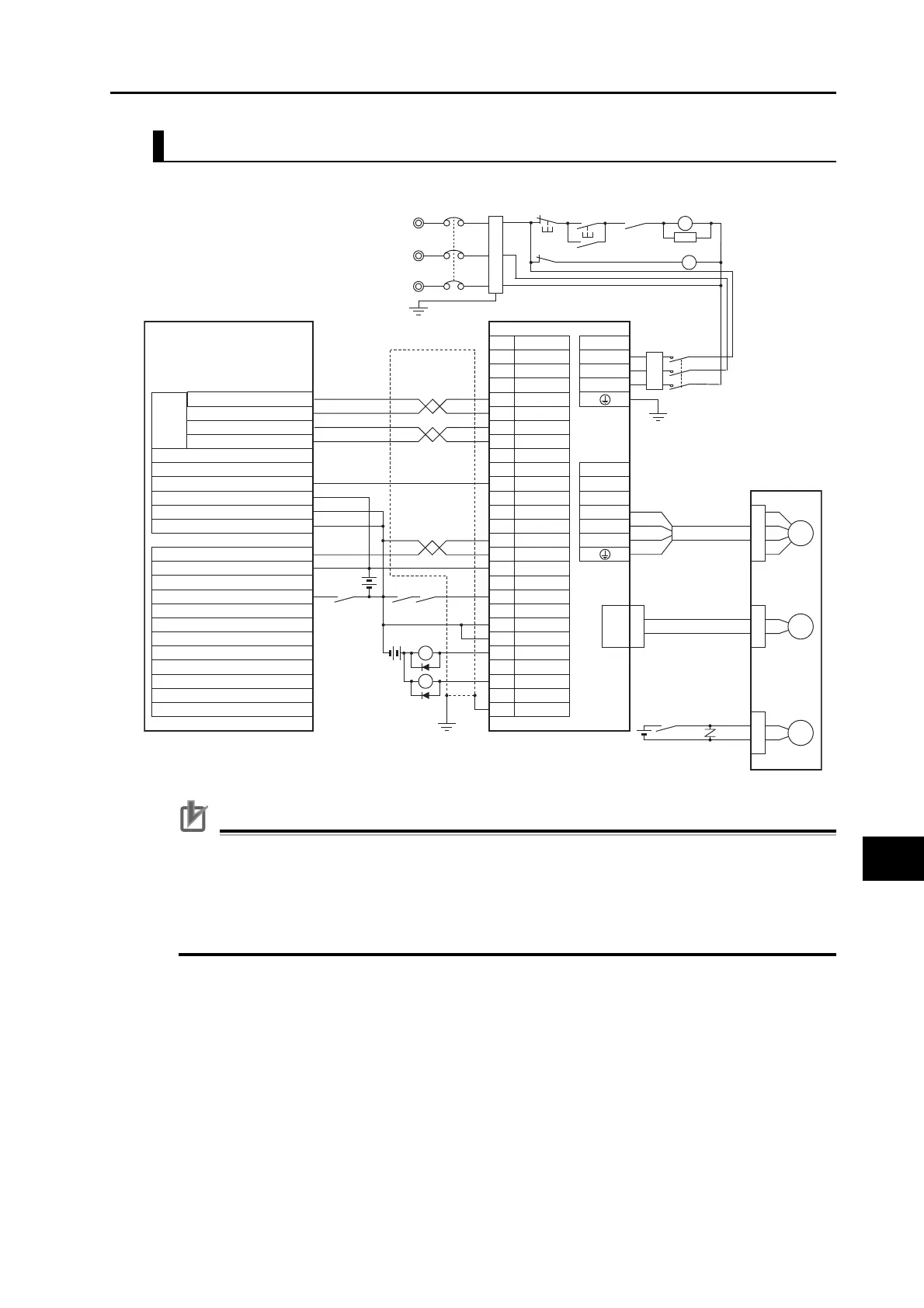
Connection Example 6: Connecting to SYSMAC CP1H-Y@@DT-D
Precautions for Correct Use
Incorrect signal wiring can cause damage to units and the drive.
Leave unused signal lines open and do not wire them.
Do not share the power supply for brakes (24 VDC) with the 24-VDC power supply for controls.
The diode recommended for surge absorption is the RU 2 (Sanken Electric Co., Ltd.) or the
equivalent.
S
CN1 CNA
4
5
6
30
39
7
29
37
11
3
L1
L2
U
V
W
ZGND
INP
RUN
/ALM
FG
Z
X1
XB
24 VDC
R
T
NFB
X1
24 VDC
BKIR
25
19
1MC
L3
M
Red
White
Blue
Green/Yellow
R88M-K@
CN2
Motor power cables
E
24 VDC
Encoder cables
B
Brake cables
XB
CNB
B1
B3
B2
BKIRCOM
10
ALMCOM
36
ECRST
X1
PL
Reactor
CP1H-Y20DT-D R88-KT@
Output terminal block
CW0+
CW0−
CCW0+
CCW0−
24-VDC input terminal (+)
Input terminal block
Shell
+CW
−CW
+CCW
−CCW
+24VIN
Pulse
Output
0
Noise filter
24-VDC input terminal (−)
COM(0CH)
Pulse 0 origin input signal (0 word, bit 00)
Pulse 0 origin proximity input signal (0 word, bit 01)
Origin search 0 (101 word, bit 02)
COM (for 101 word, bit 00 to 03)
3-phase 200 to 240 VAC 50/60 Hz
Ground to
100 Ω or less
ONOFF
X
1MC
Main circuit power supply
Main circuit contactor
1MC
surge suppressor
 Loading...


