&
2-1 Connections
The following shows an interconnection diagram. With digital operator, the
motor can be operated by wiring the main circuit only. (Terminal
shows
main circuit and
control circuit)
Important
Use listed closed-loop connectors sized for the wire gauge involved. Connec-
tors are to be installed using the correct crimp tool specified by the connector
manufacturer.
Caution
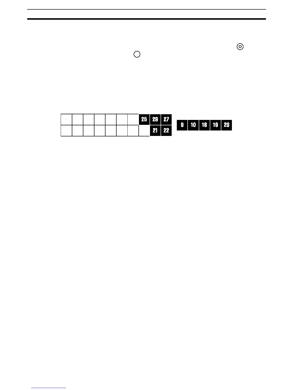
The connections of control circuit terminals 1 through 27 do not follow the
terminal numbering order. To connect them properly, follow the figure below.
11
1
12
2
13
3
14
4
15
5
16
6
17
78
Section 2-1