3-2 Drive Mode
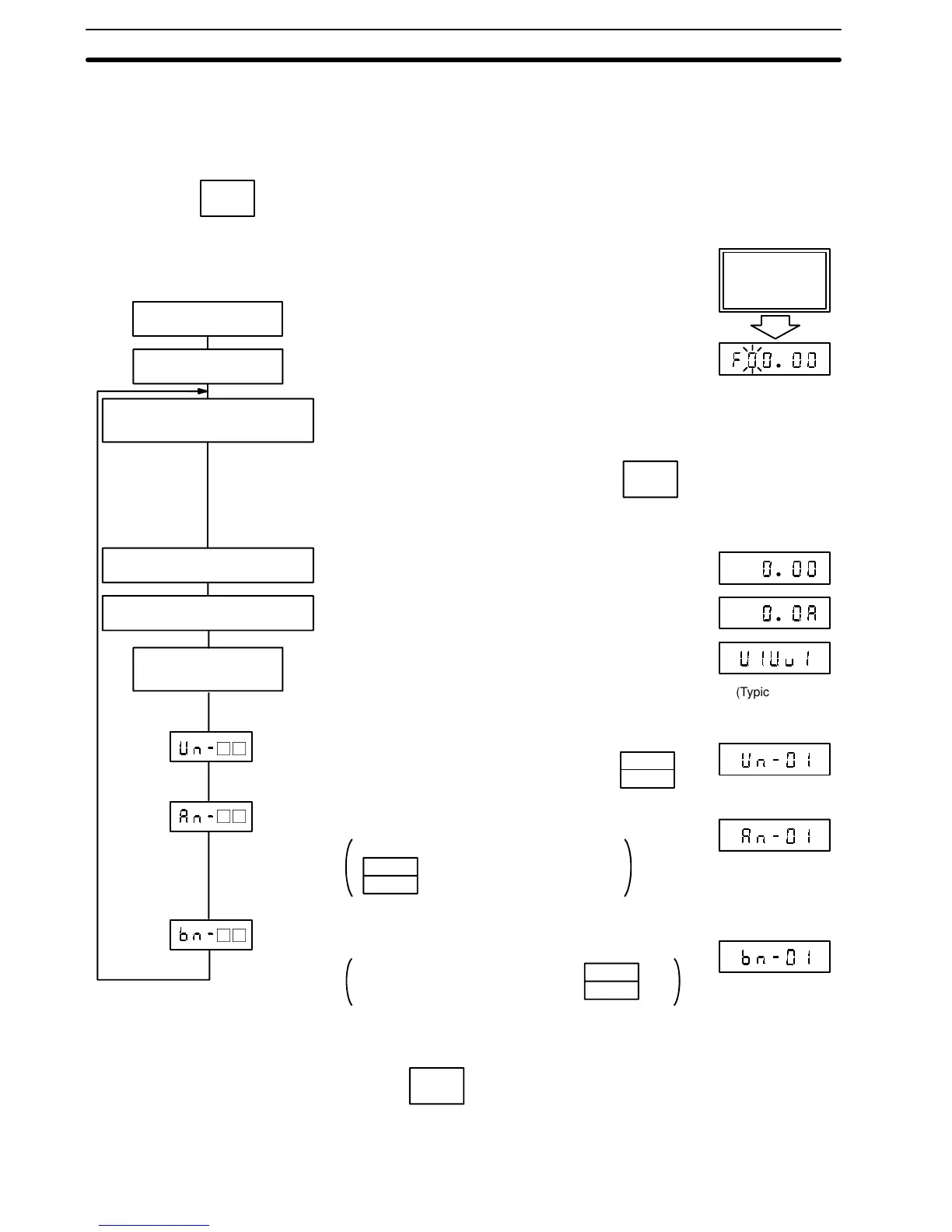
POWER SUPPLY ON
DATA
ENTER
FAULT DISPLAY
FREQUENCY REFERENCE
VALUE DISPLAY
OUTPUT FREQUENCY DISPLAY
OUTPUT CURRENT DISPLAY
RECORD OF
PAST FAULTS
DSPL
DATA
ENTER
DATA
ENTER
DSPL
DSPL
If a fault occurs, its contents are displayed and blinks for 5 sec-
onds.
Operator
Display
Set frequency is displayed. (If no fault occurs, this display is given
immediately at power supply ON, in 4 digits.)
Then the display changes as follows every time
key is depressed.
Frequency being output at present is displayed.
Inverter output current is displayed.
If a fault occurred before, its contents are displayed again.
(If no fault occurred, next constant is displayed.)
Monitor numbers such as output power are displayed.*
5-digit monitor value is displayed by depressing key.
Frequency set numbers such as master speed or inching are dis-
played.*
Depressing (display selection key)
changes the display as follows:
5-digit monitor value is displayed by depressing
key.
Constant numbers that can be changed during operation, (such as
accel/decel time) are displayed.*
Monitor value is displayed by depressing key.
*Check for display constants in APPENDIX at end of this manual
**Display changes every time key is depressed.
(Typical main
circuit undervol-
tage trip)
Section 3-2