!
4-2 Failure Indication and Details
As the table below shows, the failures that the SYSDRIVE 3G3IV detects are
classified into troubles and alarms. If a problem occurs, the fault contact is
output and the unit coasts to a stop. When an alarm is issued, the digital op-
erator indicates the alarm for warning.
Caution
Never replace the DC bus fuse without first checking the output transistors.
Failure Indication and Details
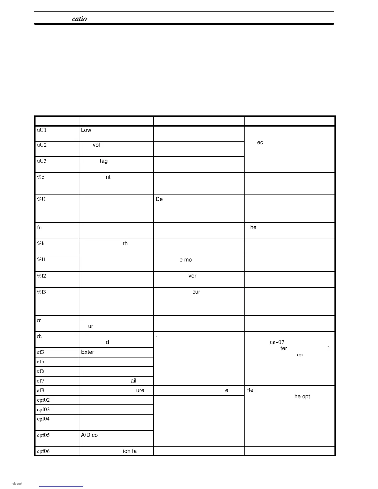
Indication Failure indication items Description Corrective action
"#
Low voltage (PUV) Two seconds are counted after the
detection of low voltage.
Check the wiring of line units (at
power supply side).
"$
Low voltage (CUV) Control circuit becomes low
voltage during operation.
Correct the power supply voltage.
"%
Low voltage (MC-ANS fault) Main circuit magnetic contactor
does not operate correctly.
&
Overcurrent Inv. output current > 120% of
transistor rated current
Check the motor winding
resistance and increase the accel
time.
&"
Overvoltage Detection level:
Approx: 400V for 200V class
Approx: 800V for 400V class
Reset level: 385V
Increase the decel time and/or
add a braking resistor.
Fuse blown --- Check short-circuit at load and
ground fault etc.
&
Radiation fin overheated Fin temperature 90
°
C (194
°
F) Check fan or ambient temperature
(less than 45
°
C, 113
°
F).
&#
Overload Protect the motor. Measure motor temperature-rise
and reduce load, then reset V/f.
&$
Overload Protect the inverter. Reduce load, and increase the
accel time, then reset V/f.
&%
Overtorque For inv. output current >
overtorque detection level and
coasting stop selection at
overtorque detection
---
Regenerative transistor
failure
--- Replace transistor.
Braking resistor unit
overheated
--- Check the state of input terminal
with data
'(
.
%
External terminal 3 failure
Replace inverter if “1” is indicated
as the state of open terminal.
)
External terminal 5 failure
.
*
External terminal 6 failure
(
External terminal 7 failure
+
External terminal 8 failure Stop mode selection possible
Replace inverter.
'$
Control circuit failure Inverter failure
Check and secure the optional
r
nn
r.
'%
NV-RAM (S-RAM) failure
.
',
NV-RAM
(BCC, Access Code)
')
A/D convertor failure in
CPU
'*
Optional connection failure --- ---
(
Section 4-2