"
Closed-Loop Connectors
Wire range
Terminal
Closed-loop connectors
AWG mm
2
screw
22 0.5 M3.5, M4 1.25 to 3.5, 1.25 to 4
18 0.75
16 1.25
14 2 M4 2to4
M5 2to5
12 3.5 M4 3.5to4
M5 3.5to5
10 5.5 M4 5.5to4
M5 5.5to5
8 8 M5 8to5
M6 8to6
6 14 M6 14 to 6
4 22 M6 22 to 8
3 30 M8 30 to 8
2 38 M8 38 to 8
2 38 M10 38 to 10
1 50 M8 50 to 8
1/0 60 M10 60 to 10
2-5 Control Circuit
The external interconnection wiring must be performed with following proce-
dures.
After completing SYSDRIVE 3G3IV interconnections, be sure to check that
connections are correct. Never use control circuit buzzer check.
(1) Separation of control circuit leads and main circuit leads:
Signal leads 1 through 20 must be separated from main circuit leads L1 (R),
L2 (S), L3 (T), B1/(+), B2, (--), B0/(--), T1 (U), T2 (V), T3 (W), and other power
cables to prevent erroneous operation caused by noise interference.
(2) Control circuit leads 9 10 18 19 20 (contact output) must be separated
from leads 1 to 8, 21 22 25 26 27 and 11 to 17.
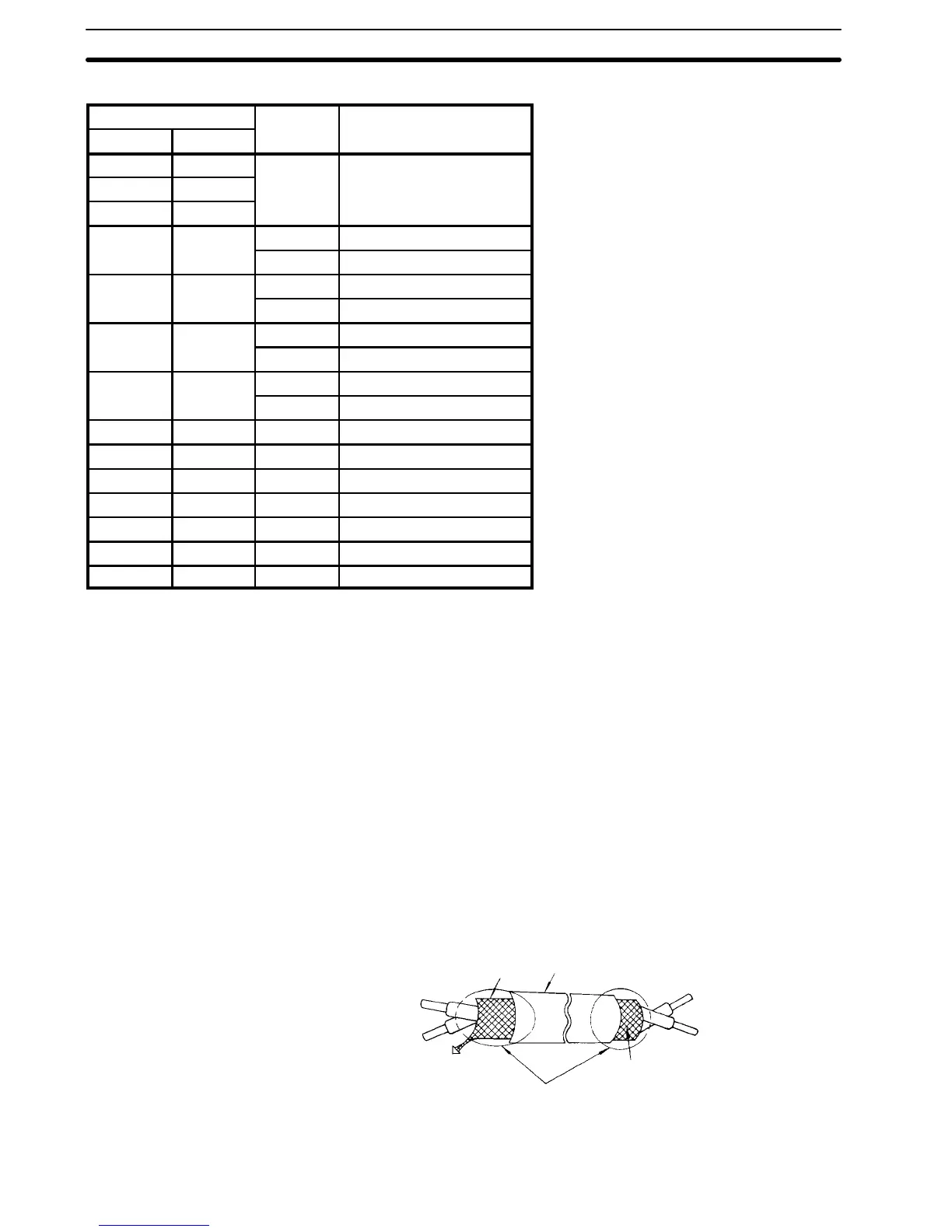
Use the twisted shielded or twisted-pair shielded lead for the control circuit
line and connect the shield sheath to the inverter terminal 12 (G). See Fig. 3.
Fig. 3 Shielded Lead Termination
SHIELD
SHEATH
ARMOR
Never connect
Insulate these parts
with insulating tape.
TO INVERTER SHIELD
SHEATH TERMINAL 12 (G)
Section 2-5