$
SPEED AGREED
SIGNAL IS SET
AT FACTORY
L1(R)
L2(S)
L3(T)
L1(R)
L2(S)
L3(T)
T1(U)
T2(V)
T3(W)
G(E)
IM
B1/ B2
BRAKING RESISTOR UNIT
(OPTIONAL)
POWER SUPPLY,
3-PHASE,
200/208/220 VAC,
50 Hz
200/208/220/
230 VAC, 60 Hz
MCCB
FORWARD
RUN/STOP
REVERSE
RUN/STOP
EXTERNAL
FAULT
FAULT RESET
MULTI-STEP SPEED
SETTING 1
(MASTER/AUX CHG.)
MULTI-STEP
SPEED SETTING 2
INCHING
COMMAND
EXTERNAL
COASTING STOP
STANDARD
FUNCTIONS
SET AT
FACTORY
PRIOR TO
SHIPMENT
1
2
3
4
5
6
7
8
11
EXTERNAL
FREQ
COMMAND
2kΩ
0TO10V
4TO20mA
0V
P
P
P
12(G)
15
13
14
16
17
MULTI-FUNCTION
INPUT
FWD
REV
Eb
RESET
FORWARD BY
HOLDING INPUT
REVERSE BY
HOLDING INPUT
ANALOG
OUTPUT
FAULT CONTACT OUTPUT
CONTACT CAPACITY
LESS THAN 1 A FOR 250 VAC
AND 30 VDC
FREQ METER (3 VDC, 1 mA)
21
22
(12)
18
19
20
9
10
25
27
MULTI-FUNCTION ANALOG
OUTPUT
STANDARD OUTPUT
FREQUENCY SETTING
OTO+10V
MULTI-FUNCTION OUTPUT
(SIGNAL DURING RUNNING IS SET AT
FACTORY PRIOR TO SHIPMENT)
CONTACT CAPACITY LESS THAN 1 A
FOR 250 VAC AND 30 VDC
SEQUENCE
COMMON
TERMINAL (0 V)
SHIELDED SHEATH
CONNECTION TERMINAL
POWER SUPPLY FOR SPEED
SETTING +15 V 20 mA
MASTER COMMAND
0TO10V(20kΩ)
MASTER COMMAND
4TO20mA
(250 kΩ)
MULTI-FUNCTION
ANALOG INPUT
0TO10V(20kΩ)
26
MULTI-FUNCTION
OUTPUT OPEN
COLLECTOR 2
MULTI-FUNCTION
OUTPUT OPEN
COLLECTOR 1
”0 SPEED SIGNAL”
IS SET AT FACTORY
MOTOR
SYSDRIVE 3G3IV
0V
FM
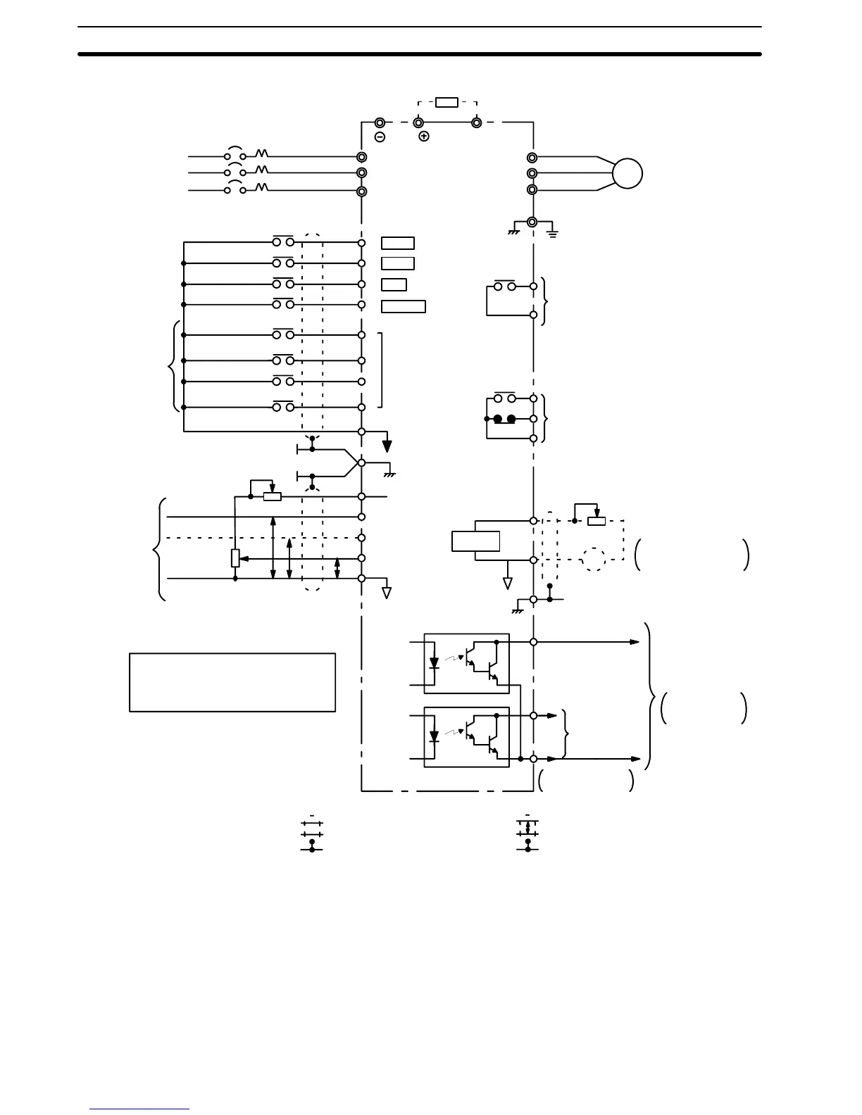
Switching between master frequency command at
external terminal 13 or 14 and aux. frequency
command at 16 corresponds to the master/aux.
selection contact input.
IMPORTANT
AUX
FREQ
SETTING
2kΩ
3*
3*
FREQ METER CALIBRATION
RESISTOR RV30YN 20SB 20 kΩ
+--
Fig. 2 Interconnections
Example of Model 3G3IV-A2007-E.
Note
1.
indicates shielded leads and
P
twisted-pair shielded leads.
2. External terminal 15 of +15V has maximum output current capacity of
20mA.
3. Either external terminal 13 or 14 can be used.
4. Multi-function analog output is an exclusive meter output such as frequen-
cy meter etc. and not available for the feed back control system. Use ana-
log monitor cards (Model PAO08 or PAO12) for the control system.
5. 12(G) indicates inverter frame earth ground.
6. Install an input RFI filter when operating at a high carrier frequency.
7. Use shielded cable if the motor is more than 30 m from the Inverter.
8. Use an AC reactor when driving more than one motor with one Inverter.
Section 2-1