24
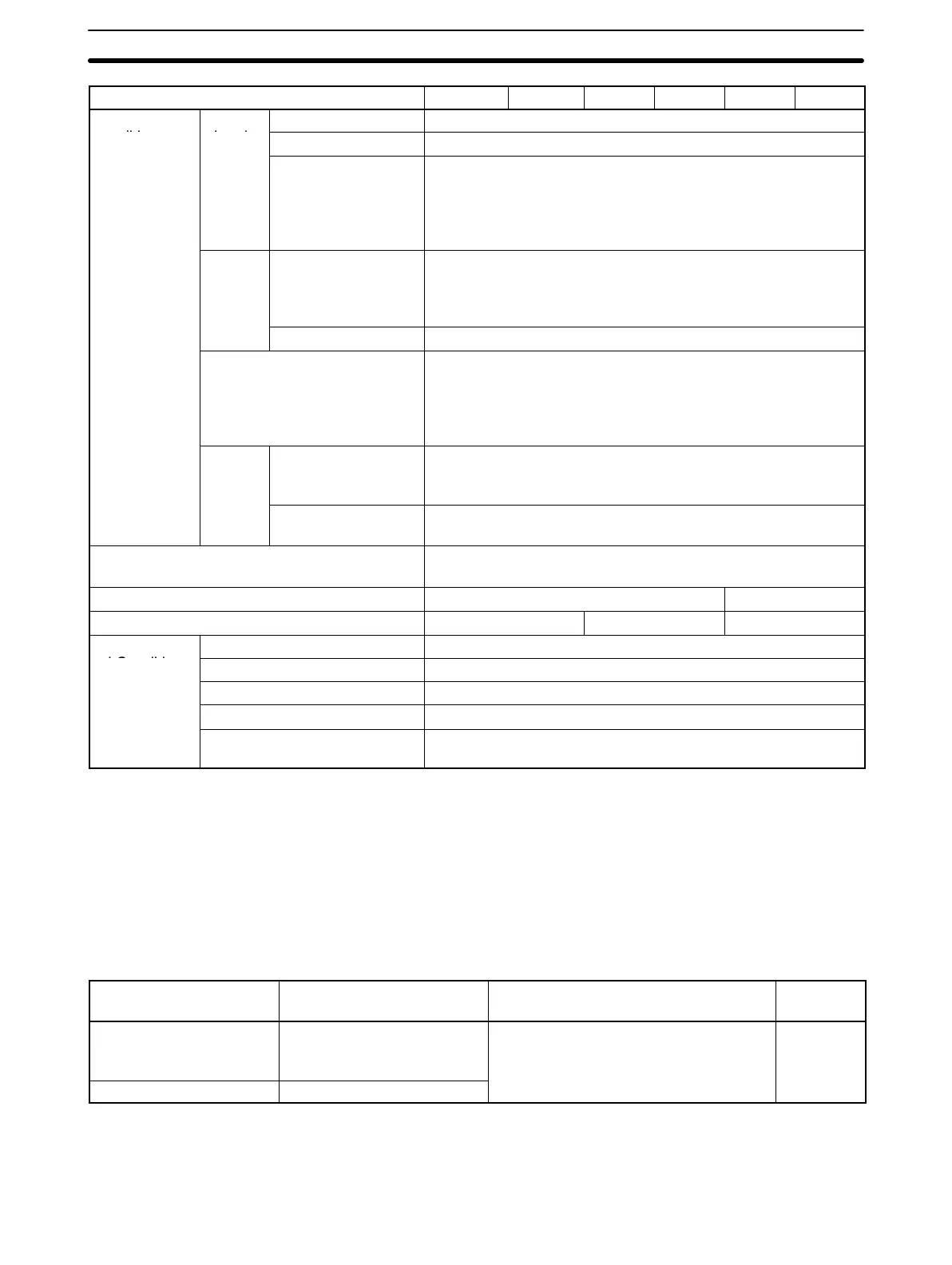
Inverter Model 3G3XV--EV2
A4037A4022A4015A4007A4004A4002
Operation
Input
Operation signal Forward operation/reverse operation by individual command
conditions signals
Reset Releases protection while the function is operating.
Multifunction input
selection
Multifunction contact input: two of the following signals avail-
able to select.
External fault multispeed command, jog operation, accel/
decel time select, 3-wire sequence, external coasting stop,
speed search command.
Output
signals
Operation state
(photo-coupler out-
put)
Multifunction contact output: two of the following signals
available to select.
During running output, zero speed, frequency agree, output
frequency ≥ setting value, during overtorque detection
Fault contact NO/NC contact output
Built-in functions The following set-up is available: frequency reference bias/
gain, upper/lower frequency limit, DC braking stop current at
start, torque boost, frequency meter calibrating gain, fre-
quency jump, S-curve characteristics, auto reset/restart
operation.
Monitor
display
function
Digital Operator Displays setting frequency, output frequency, output current,
rotating direction, and the contents at protective function
operation.
Analog output mon-
itor
Analog output (0 to 10 VDC). Possible to select output fre-
quency or output current.
Protective configuration Enclosed wall-mounted type NEMA 1
(An open chassis type is also available.)
Cooling method Self-cooling Forced cooling
Weight in lb (kg) 4.4 (2) 6.6 (3) 11.0 (5)
Environmen-
Location Indoor (protected from corrosive gases and dust)
tal Conditions
Ambient temperature +14° to 104°F (–10° to +40°C) (not frozen)
Storage temperature
2
–4° to 140°F (–20° to +60°C)
Humidity 90% RH (without condensation)
Vibration Up to 9.8 m/s
2
(1 g) at less than 20 Hz.
Up to 2 m/s
2
(0.2 g) at 20 to 50 Hz.
Note 1. Use a standard 4-pole motor for maximum applicable motor
output.
2. Temperature during shipping (for short period).
1-6-3 Optional Units
Name Model (code no.) Function Installing
position
Braking Resistor Unit
3G3IV-PLKEB
Shortens the motor deceleration time
by causing the regenerative energy to
be consumed through the resistor.
Separately
installed
Braking Resistor
3G3IV-PERF150WJ
Note When using the Braking Resistor Unit or Braking Resistor, set the
stall prevention during deceleration (n%20) to “1” (disabled).
Specifications Section 1-6

 Loading...


