5
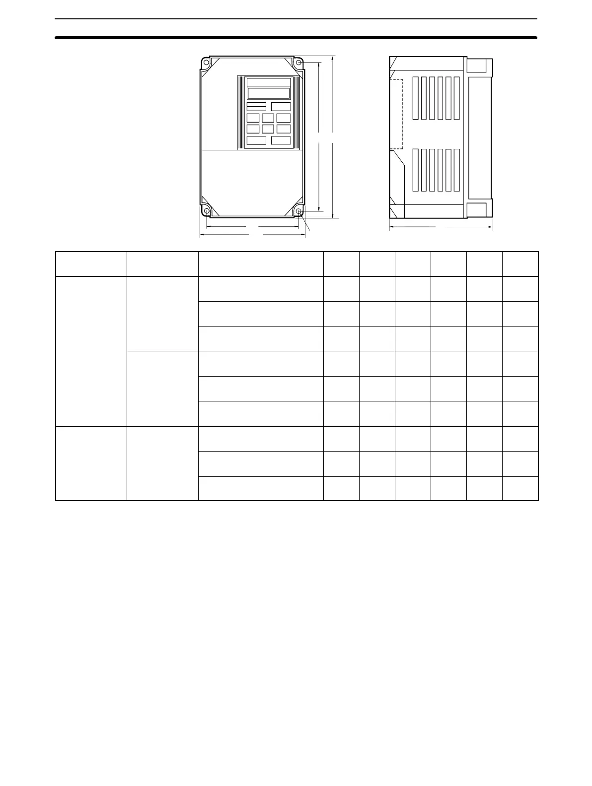
W1
W
H1 H
Four, d dia.
D
Voltage Phase Max. Applicable
Motor Output HP (kW)
W W1 H H1 D d
200 V 3-phase 0.13 to 0.5 (0.1 to 0.4) 4.13
(105)
3.66
(93)
5.91
(150)
5.43
(138)
3.94
(100)
0.20
(5)
1/2 (0.75/1.5) 5.51
(140)
5.04
(128)
5.91
(150)
5.43
(138)
5.43
(138)
0.20
(5)
3/5 (2.2/3.7) 5.51
(140)
4.96
(126)
7.87
(200)
7.32
(186)
6.69
(170)
0.22
(5.5)
Single-phase 0.13 to 0.5 (0.1 to 0.4) 5.51
(140)
5.04
(128)
5.91
(150)
5.43
(138)
5.43
(138)
0.20
(5)
1/2 (0.75/1.5) 5.51
(140)
4.96
(126)
7.87
(200)
7.32
(186)
6.69
(170)
0.22
(5.5)
3/5 (2.2/3.7) 7.48
(190)
6.89
(175)
7.87
(200)
7.28
(185)
7.48
(190)
0.23
(5.8)
400 V 3-phase 0.25/0.5 (0.2/0.4) 5.51
(140)
4.96
(126)
7.87
(200)
7.32
(186)
4.72
(120)
0.22
(5.5)
1/2 (0.75/1.5) 5.51
(140)
4.96
(126)
7.87
(200)
7.32
(186)
6.69
(170)
0.22
(5.5)
3/5 (2.2/3.7) 7.48
(190)
6.89
(175)
7.87
(200)
7.28
(185)
7.48
(190)
0.23
(5.8)
1-4 Wiring
Connect the main circuit and control circuit wiring securely, as
described below.
Note Use closed-loop connectors sized for the gauge of wire being
used. Attach the connectors using a crimping tool recommended
by the connector manufacturer.
1-4-1 Terminal Blocks
The main circuit and control circuit terminal blocks are at the bot-
tom of the Inverter under a terminal cover.
Removing/Attaching the Terminal Cover
To remove the terminal cover, squeeze the sides of the cover (1),
and lift up (2) at the same time, as shown in the following diagram.
Reverse these steps to attach the cover.
Wiring Section 1-4

 Loading...


