38
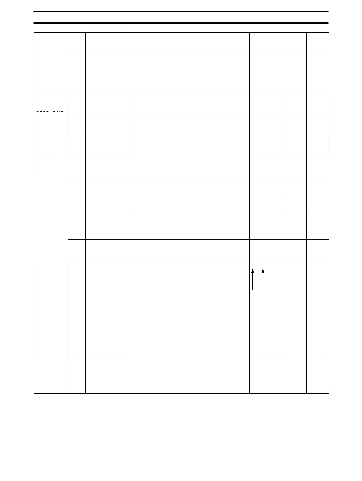
Function See
page
User
set
values
Initial
setting
DescriptionNameNo.
V/f char-
acteristic
7 Minimum out-
put frequency
Setting unit: 0.1 Hz, setting range; 0.1 to
10 Hz
1.5 Hz 45
setting
8 Minimum out-
put frequency
voltage
Setting unit: 0.1 V, setting range: 0.1 to 50
V
12.0 V
(Note 1)
45
First
accel/
decel time
9 Acceleration
time 1
Setting unit: 0.1 s, setting range: 0.0 to
600.0 s
10.0 s 48
setting
(see note
2)
10 Deceleration
time 1
Setting unit: 0.1 s, setting range: 0.0 to
600.0 s
10.0 s 48
Second
accel/
decel time
11 Acceleration
time 2
Setting unit: 0.1 s, setting range: 0.0 to
600.0 s
10.0 s 48
setting
(see note
2)
12 Deceleration
time 2
Setting unit: 0.1 s, setting range: 0.0 to
600.0 s
10.0 s 48
Frequency
reference
13 Frequency
reference 1
Setting unit: 0.1 Hz, setting range: 0.0 to
400.0 Hz
0.0 Hz 47
(see note
2)
14 Frequency
reference 2
Setting unit: 0.1 Hz, setting range: 0.0 to
400.0 Hz
0.0 Hz 47
15 Frequency
reference 3
Setting unit: 0.1 Hz, setting range: 0.0 to
400.0 Hz
0.0 Hz 47
16 Frequency
reference 4
Setting unit: 0.1 Hz, setting range: 0.0 to
400.0 Hz
0.0 Hz 47
17 Jogging fre-
quency refer-
ence
Setting unit: 0.1 Hz, setting range: 0.0 to
400.0 Hz
6.0 Hz 47
Electronic
thermal
overload
motor
protection
18 Motor protec-
tion selection
1
st
digit = 0: Electronic thermal overload
motor protection provided
1: Electronic thermal overload
motor protection not pro-
vided
2
nd
digit = 0: Electronic thermal overload
characteristic is for standard
motor
1: Electronic thermal overload
characteristic is for constant
torque motor
3
rd
digit Not used
4
th
digit: Not used
0000
1
st
digit
4
th
digit
49
Electronic
thermal
overload
reference
current
19 Motor rated
current
Setting unit: 0.1 A, setting range: 10% to
120% of Inverter rated current
1.9 A (see
note 3)
49
Note 1. Values for the 400-V Class are twice those for the 200-V Class.
2. Can be changed even during run.
3. Initial setting differs according to the Inverter capacity. the val-
ues in the above list are provided when Model 3G3XV-A2004
Function/Constant List Section 2-7

 Loading...


