21
1-6 Specifications
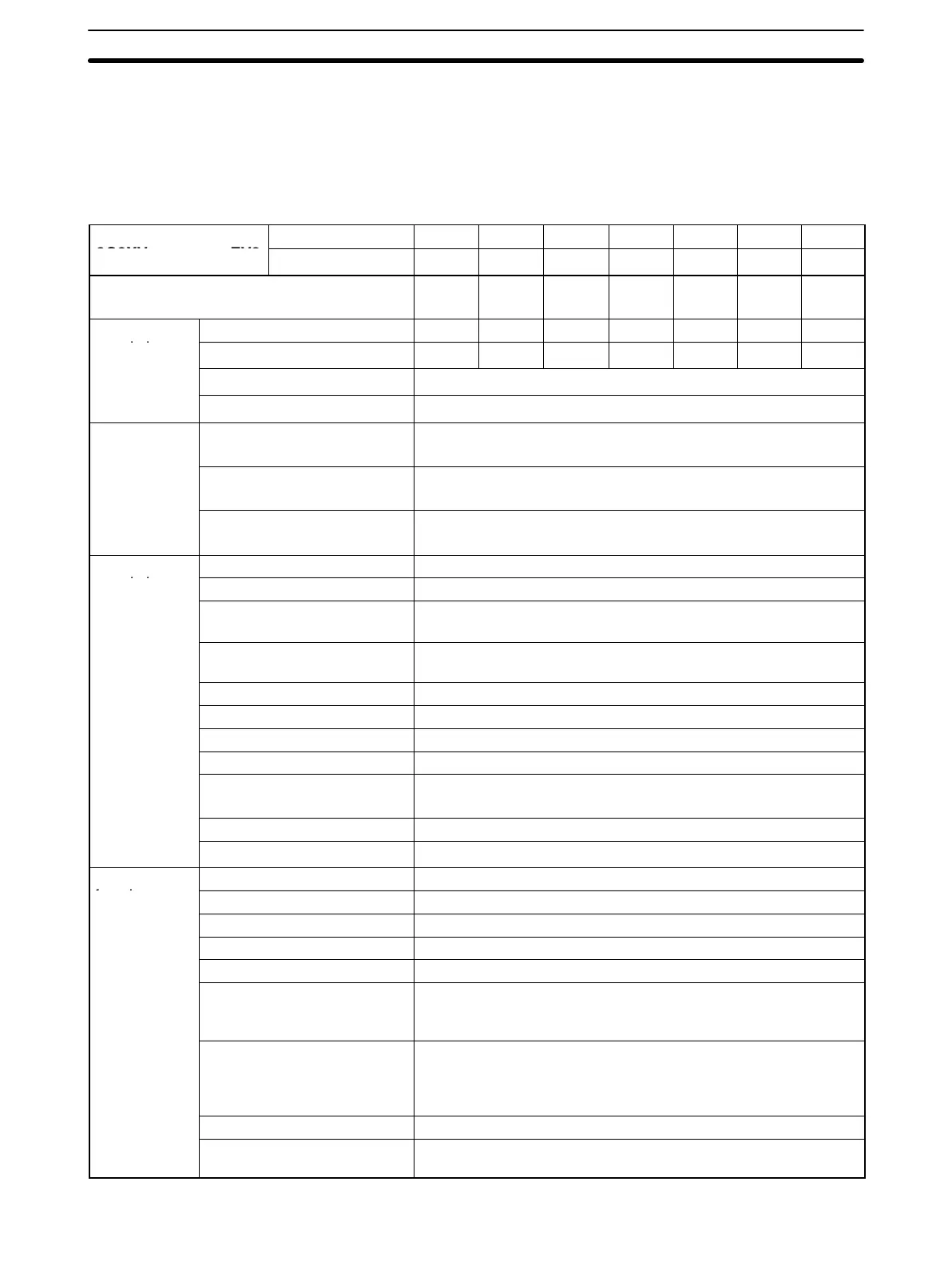
1-6-1 200-V-class Specifications
Inverter Model
3-phase A2001 A2002 A2004 A2007 A2015 A2022 A2037
3G3XV--EV2
Single-phase AB001 AB002 AB004 AB007 AB015 AB022 AB037
Max. applicable motor output Hp (kW)
(see note 1)
0.13
(0.1)
0.25
(0.2)
0.5
(0.4)
1
(0.75)
2 (1.5) 3 (2.2) 5 (3.7)
Output char-
Inverter capacity (kVA) 0.3 0.6 1.1 1.9 2.5 4.2 6.7
acteristics
Rated output current (A) 0.8 1.5 3 5 6.5 11 17.5
Max. output voltage 3-phase, 200 to 230 V (proportional to input voltage)
Max. output frequency 400 Hz (available with constant setting)
Power supply Rated input voltage and fre-
quency
3-phase: 200 to 230 V, 50/60 Hz
Single-phase: 200 to 240 V, 50/60 Hz
Allowable voltage fluctua-
tion
10%
Allowable frequency fluctua-
tion
5%
Control char-
Control method Sine wave PWM
acteristics
Frequency control range 0.1 to 400 Hz
Frequency accuracy Digital command: 0.01% +14° to 104°F, –10° to 40°C
Analog command: 0.1% 77°18°F, 25°10°C
Frequency resolution Digital Operator reference:0.1 Hz.
Analog reference: 0.06 Hz/60 Hz
Output frequency resolution 0.1 Hz
Overload capacity 150% rated output current for one minute
Frequency setting signal 0 to 10 VDC (20 kΩ), 4-20 mA (250 Ω)
Accel/decel time 0.1 to 600 sec (accel/decel time setting independently)
Braking torque Approx. 20% (up to 150% possible with optional braking resis-
tor externally mounted)
V/f characteristic Possible to set any program of V/f pattern
Stall prevention level Effective by current limiting at start and during running.
Protective
Instantaneous overcurrent Motor coasts to a stop at approx. 200% rated current.
functions
Overload Motor coasts to stop in 60 sec. at 150% rated output current
Ground fault Provided by electronic circuit.
Motor overload protection Electronic thermal overload relay
Overvoltage Motor coasts to stop if main circuit DC voltage exceeds 410 V
Undervoltage Motor coasts to a stop if the main circuit DC voltage of a
3-phase Model drops to 210 V or below and that of a Single-
phase Model drops to 170 V or below.
Momentary power loss Immediately stops if 15 ms or more momentary power loss.
Resumes operating after a power loss period of approxi-
mately 2 s if the input is 1.5 kW or more and approximately 1
s if the input is 0.75 kW or less in a certain mode.
Cooling fin overheat Protected by thermoswitch (only for forced cooling method)
Power charge indication CHARGE indicator stays ON until main circuit DC voltage
drops below 50 V.
Specifications Section 1-6

 Loading...


