8
4. When using the optional braking resistor (3G3IV-
PERF150WJ), place a thermal overload relay between the
braking resistor and Inverter to prevent the braking resistor
from overheating. In addition, use a sequencer to break the
power supply side on the thermal overload relay trip contact.
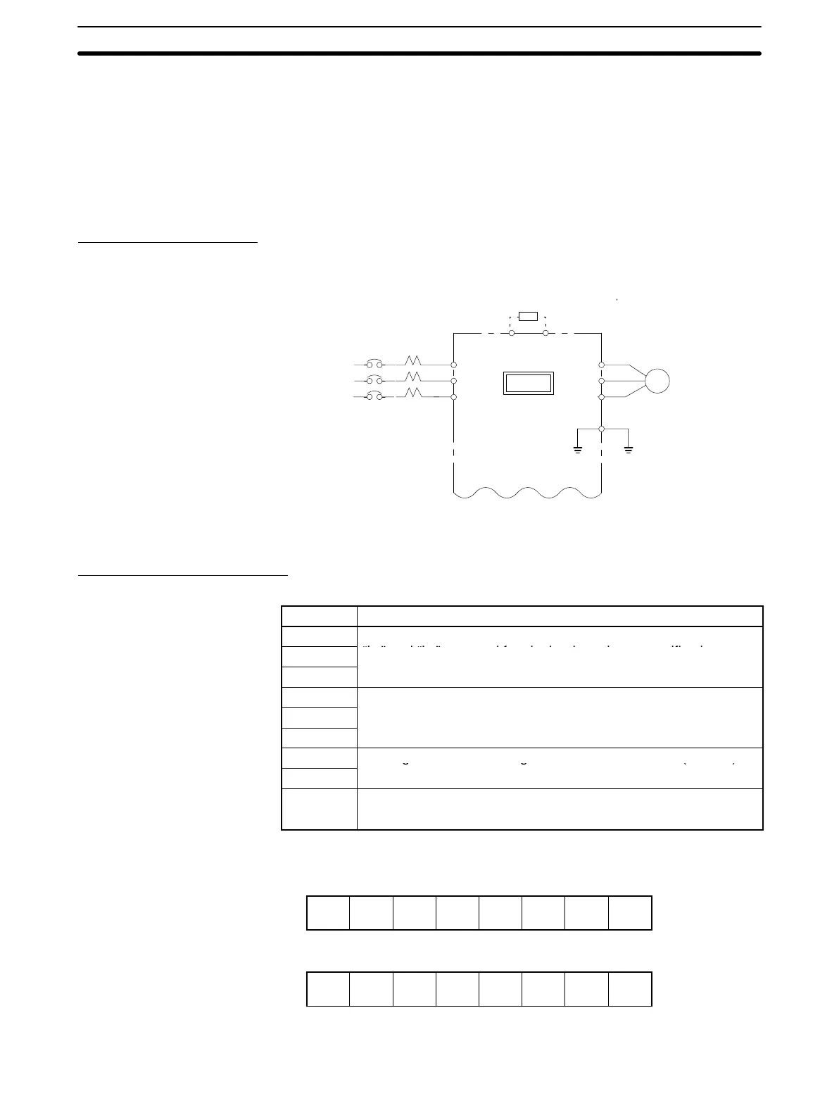
1-4-3 Main Circuit
Main Circuit Wiring
Connect wiring as shown below.
IM
L1 (R)
L2 (S)
L3 (T)
L1 (R)
L2 (S)
L3 (T)
T1 (U)
T2 (V)
T3 (W)
G(E)
B1/⊕ B2
Motor
MCCB
3-phase power supply
200 to 230 VAC, 50/60 Hz,
380 to 460 VAC, 50/60 Hz
Braking resistor or
Braking Resistor Unit (optional)
Only terminal L1 (R), L2 (S)
for single-phase power supply
3G3XV
Note Circuit terminal block screw size is M4
Main Circuit Terminals
3G3XV Main Circuit Terminals
Terminal Description
L
1
(R)
Main circuit power input
“L ”d“L” d f i l h i ifi i
L
2
(S)
“L
1
” and “L
2
” are used for single-phase input specifications.
L
3
(T)
T
1
(U)
Inverter output
T
2
(V)
T
3
(W)
B1/⊕
Braking resistor or Braking Resistor Unit connector (options)
B2
G (E) Grounding (Ground resistance should be 100 ohms or less.)
Note: Use screw for frame ground.
Main Circuit Terminal Arrangement
3-phase series (all Models):
L
1
(R)
L
2
(S)
L
3
(T)
B
1
/⊕ B
2
T
1
(U)
T
2
(V)
T
3
(W)
200-V single-phase series, 0.13 to 2 HP (0.1 to 1.5 kW):
L
1
(R)
L
2
(S)
B
1
/⊕ B
2
T
1
(U)
T
2
(V)
T
3
(W)
Note The third terminal is blank.
Wiring Section 1-4

 Loading...


