9 Quick-response Inputs
9-3
CP2E CPU Unit Software User’s Manual(W614)
9-1 Quick-response Inputs
9
9-1-2 Flow of Operation
Precautions for Correct UsePrecautions for Correct Use
A built-in input cannot be used as a quick-response input if it is being used as a normal input,
interrupt input, or high-speed counter input. Refer to 8-3-3 Allocating Built-in Input Terminals for
details.
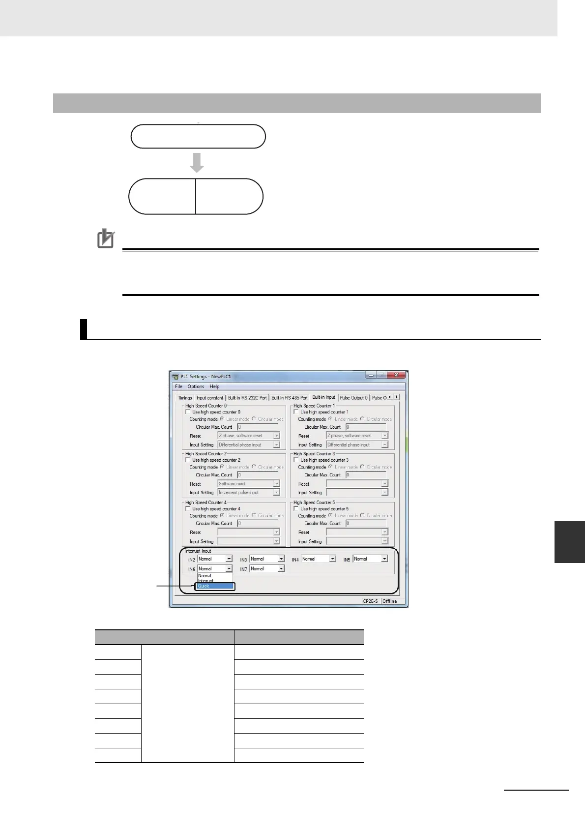
Click the Built-in Input Tab and select Quick in the interrupt input settings.
Built-in Input Tab Page
9-1-2 Flow of Operation
1
• Set IN2 to IN9 for quick-response inputs on the Built-in Input
Tab Page of the PLC Setup using the CX-Programmer.
• The terminals 02 to 09 of CIO 0 can be used for quick-
response inputs. Bits CIO 0.02 to CIO 0.09 correspond to ter-
minals 02 to 09.
2
Read the status of CIO 0.02 to CIO 0.09 using the LD instruction
or other instructions.
PLC Setup
Quick-response input setting Corresponding bit address
IN2 Select Quick for IN2
to IN9.
CIO 0.02
IN3 CIO 0.03
IN4 CIO 0.04
IN5 CIO 0.05
IN6 CIO 0.06
IN7 CIO 0.07
IN8 CIO 0.08
IN9 CIO 0.09
PLC Setup
Create ladder
program
Cyclic task or
interrupt task
Select Quick