12 Pulse Outputs
12-34
CP2E CPU Unit Software User’s Manual(W614)
Execute the ORG instruction in the ladder program to perform an origin search with the specified
parameters.
Precautions for Correct UsePrecautions for Correct Use
Limit Sensor Application
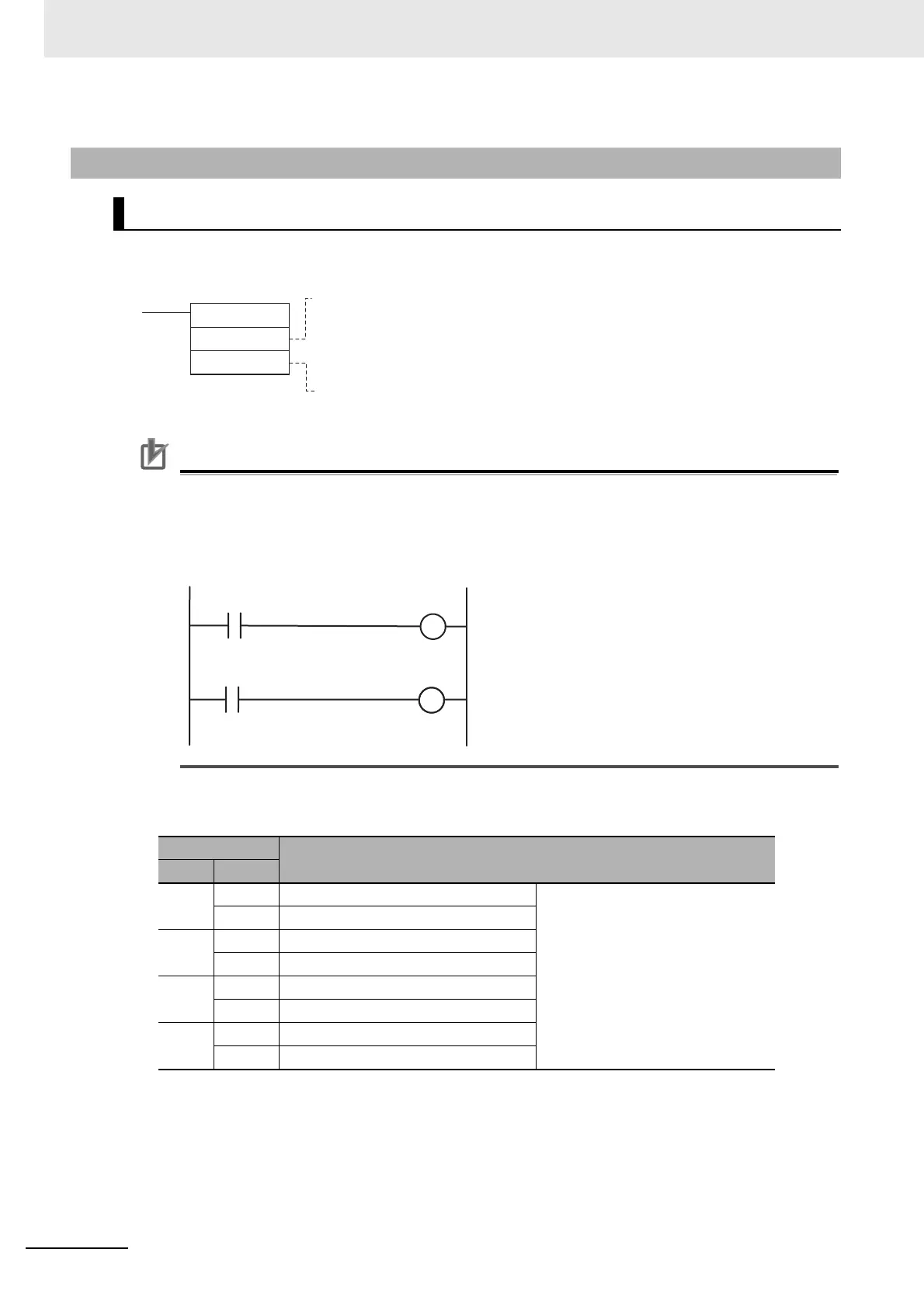
Create a program that can identify the limit sensor when using the origin search.
The OUT instruction is used in the ladder program to write signals received from the CW limit
sensor and CCW limit sensor connected to normal inputs to the Auxiliary Area bits.
Bits Written in the Auxiliary Area
12-6-4 Origin Search Instructions
Origin Search Instruction: ORG
Auxiliary Area
Name
Word Bit
A540 08 Pulse Output 0 CW Limit Input Signal Signals received from external sen-
sors connected to normal inputs
must be written to the Auxiliary Area
bits in the user program.
09 Pulse Output 0 CCW Limit Input Signal
A541 08 Pulse Output 1 CW Limit Input Signal
09 Pulse Output 1 CCW Limit Input Signal
A542
08 Pulse Output 2 CW Limit Input Signal
09 Pulse Output 2 CCW Limit Input Signal
A543
08 Pulse Output 3 CW Limit Input Signal
09 Pulse Output 3 CCW Limit Input Signal
ORG
C1
C2
C1:Port specifier
Pulse output 0: #0000
Pulse output 1: #0001
Pulse output 2: #0002
Pulse output 3: #0003
C2:Control data
Origin search and pulse + direction output method: #0100
Normal input from CW
limit sensor
CW Limit Input Signal
A540.08, A541.08,
A542.08 or A543.08
Normal input from CCW
limit sensor
CCW Limit Input Signal
A540.09, A541.09,
A542.09 or A543.09