14 Serial Communications
14-44
CP2E CPU Unit Software User’s Manual(W614)
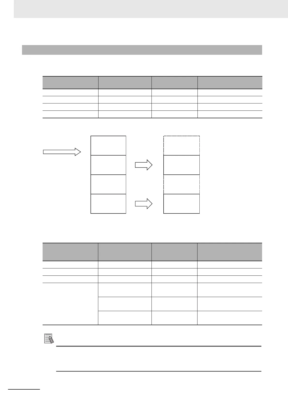
Modbus has the following four common data models.
CP2E allocates each area of these data models to an I/O Memory area.
z CP2E Fixed Allocations
The following table gives the relationship between Modbus data model and CP2E I/O memory of CP2E
CPU unit.
Additional Information
Addresses in Modbus data models start from 1, but addresses specified in Modbus-RTU com-
mands and addresses in the CP2E CPU Unit start from 0. Refer to the above table when speci-
fying addresses in applications.
14-7-4 Operation Specifications
Modbus data model Data type Read/Write
CP2E CPU unit
I/O Memory allcation
Discrete Inputs Bit read None
Coils Bit read Auxiliary Area (W)
Input Registers Word (16 bit) read/write None
Holding Registers Word (16 bit) read/write Data Memory (D)
Modbus data model Modbus address
Address specified
in Modbus-RTU
commands
Corresponding CP2E I/O
Memory address
Discrete Inputs --- --- ---
Coils 1 to 2048 0 to 2047 W0.00 to W127.15
Input Registers --- --- ---
Holding Registers 1 to 4096 0 to 4095 CP2E E-type
D0 to D4095
1 to 8192 0 to 8191 CP2E S-type
D0 to D8191
1 to 16384 0 to 16383 CP2E N-type
D0 to D16383
Modbus Data Models CP2E CPU Unit
I/O Memory
Modbus-RTU Command
Read Coils
Discrete
Inputs
None
Auxiliary Area
(W)
Coils
0
1
Read Holding Registers
Write Single Register
Write Multiple Coils
Write Multiple Registers
Input
Registers
None
Holding
Registers
Data Memory
(D)
0
1
2
:
0
1
2
:
0
1
2
:
0
1
2
:
:
0
1
2
:
2