EasyManua.ls Logo

Omron SYSMAC CP2E-E D Series User Manual

Omron SYSMAC CP2E-E D Series
578 pages
To Next Page IconTo Next Page
To Previous Page IconTo Previous Page
Page #74 background imageLoading...
Page #74 background image
4 Understanding Programming
4-30
CP2E CPU Unit Software User’s Manual(W614)
z Direct Addressing of Index Registers
The size of an index registers is two words per register for Index Registers IR0 to IR15, so use a
double-word instruction (with an “L” in the mnemonic).
It is possible to monitor Index Registers as follows:
To use the CX-Programmer to monitor the final Index Register values for each task.
To monitor the Index Register values using Host Link commands or FINS commands, write a pro-
gram to store Index Register values from each task to another area (e.g., DM area) at the end of each
task, and to read Index Register values from the storage words (e.g., DM area) at the beginning of
each task. The values stored for each task in other areas (e.g., DM area) can then be edited using
the CX-Programmer, Host Link commands, or FINS commands.
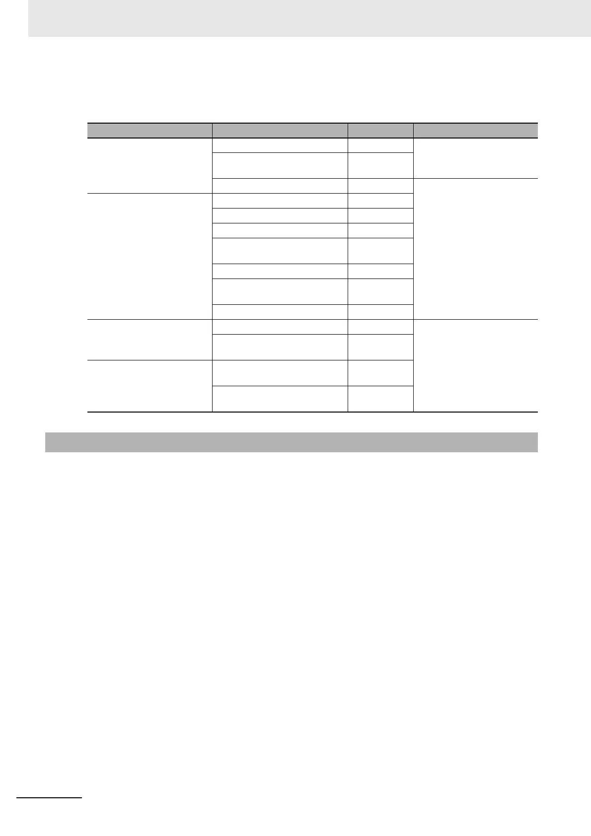
Instruction group Instruction name Mnemonic Primary function
Data Movement Instructions MOVE TO REGISTER MOVR(560) Stores the PLC memory
address of a bit or word in an
Index Register.
MOVE TIMER/COUNTER PV
TO REGISTER
MOVRW(561)
DOUBLE MOVE MOVL(498) Transfers between Index
Registers. Used for
exchanges and comparisons.
Comparison Instructions
DOUBLE EQUAL =L(301)
DOUBLE NOT EQUAL < >L(306)
DOUBLE LESS THAN < L(311)
DOUBLE LESS THAN OR
EQUAL
< =L(316)
DOUBLE GREATER THAN >L(321)
DOUBLE GREATER THAN OR
EQUAL
>=L(326)
DOUBLE COMPARE CMPL(060)
Increment/Decrement
Instructions
DOUBLE INCREMENT BINARY ++L(591) Changes the PLC memory
address in the Index Register
by incrementing, decrement-
ing, or offsetting its content.
DOUBLE DECREMENT
BINARY
−−L(593)
Symbol Math Instructions
DOUBLE SIGNED BINARY
ADD WITHOUT CARRY
+L(401)
DOUBLE SIGNED BINARY
SUBTRACT WITHOUT CARRY
L(411)
4-6-3 Monitoring Index Registers

Table of Contents

Question and Answer IconNeed help?

Do you have a question about the Omron SYSMAC CP2E-E D Series and is the answer not in the manual?

Omron SYSMAC CP2E-E D Series Specifications

General IconGeneral
Input Voltage24V DC
Data MemoryUp to 32 KB
TypeProgrammable Logic Controller (PLC)
CPU TypeRISC
Communication PortsRS-232C, RS-485
Ethernet PortYes
USB PortYes
Serial Port1 x RS-232C
High-speed CounterYes
Pulse OutputYes
Interrupt InputsYes (4 inputs)
Expansion Slots2
Operating Temperature0°C to 55°C
Dimensions90 x 90 x 70 mm
SeriesCP2E-E D Series

Summary

SYSMAC CP Series

CP2E CPU Unit Software User’s Manual

User's Manual for CP2E CPU Unit Software.

Introduction

CP2E CPU Unit Manuals

CP2E CPU Unit Software User’s Manual (This Manual)

Describes software specifications, operation, memory, programming, and functions.

CONTENTS

Safety Precautions

Provides critical safety information for using the PLC.

Precautions for Safe Use

Details precautions for handling and external circuits for safe operation.

Section 2 Internal Memory in the CPU Unit

Details the types of internal memory and stored data in the CPU Unit.

Section 3 CPU Unit Operation

Explains CPU Unit operation, modes, and behavior during power interruptions.

Section 4 Understanding Programming

Covers basic information on ladder programming for CP2E CPU Units.

4 Understanding Programming

4-1 Programming

Covers user programs, data, and programming languages.

4-4 Programming Instructions

Details instructions, operands, variations, execution conditions, data formats, and I/O refresh.

Section 5 I/O Memory

Describes the types of I/O memory areas and their details.

Section 7 PLC Setup

Details parameters for basic settings of the CP2E CPU Unit.

7 PLC Setup

7-2 PLC Setup Settings

Covers settings for startup, timing, interrupts, inputs, and outputs.

7-2 PLC Setup Settings

Covers settings for startup, timing, interrupts, inputs, serial ports, pulse outputs, and Ethernet.

Terms and Conditions Agreement

Warranty, Limitations of Liability

Outlines warranty, limitations of liability, and buyer remedies.

Limitation on Liability; Etc

States OMRON COMPANIES SHALL NOT BE LIABLE FOR SPECIAL, INDIRECT, INCIDENTAL DAMAGES.

Precautions for Safe Use

Handling

Precautions for proper unit setting, DIP switches, DM Area initialization, and program checks.

Related Manuals

SYSMAC CP Series CP2E CPU Unit Software User’s Manual (this manual)

Describes software specifications, CPU Unit operation, programming, and functions.

1 Overview

1-2 Basic Operating Procedure

Outlines the general procedure for setting up and operating the CP2E.

2 Internal Memory in the CPU Unit

2-1 Internal Memory in the CPU Unit

Details the types of internal memory and stored data in the CPU Unit.

3 CPU Unit Operation

3-1 CPU Unit Operation

Describes CPU Unit operation, modes, and behavior during power interruptions.

3-2 Backing Up Memory

Explains data backup to built-in Flash Memory and non-volatile RAM.

5 I/O Memory

5-1 Overview of I/O Memory Areas

Describes I/O memory areas: CIO, Work, Holding, Data, Timer, Counter, Index, Data Registers, System Areas.

6 I/O Allocation

6-1 Allocation of Input Bits and Output Bits

Explains OMRON's term for allocating I/O bits and how the CPU Unit allocates them to expansion units.

8 Overview of Built-in Functions and Allocations

8-2 Overall Procedure for Using CP2E Built-in Functions

Describes the steps to select, configure, create programs, transfer, and start using functions.

9 Quick-response Inputs

10 Interrupts

10-2 Input Interrupts

Explains input interrupts that execute tasks when built-in inputs turn ON or OFF.

11 High-speed Counters

11-1 Overview

Describes using high-speed counters for measuring pulse input signals and applications.

11-2 High-speed Counter Inputs

Details pulse input methods, counting ranges, reset methods, and frequency measurement.

11-3 High-speed Counter Interrupts

Explains executing interrupt tasks based on counter PV comparison with target values or ranges.

12 Pulse Outputs

12-2 Positioning Control

Describes using pulse outputs with trapezoidal acceleration/deceleration.

12-6 Defining Origin Position

Describes methods to define origin position using origin search or PV changes.

13 PWM Outputs

13-1 PWM Outputs (Variable-duty-factor Pulse Outputs)

Describes PWM outputs, including application examples and specifications.

14 Serial Communications

14-4 Modbus-RTU Easy Master Function

Explains using Modbus-RTU Easy Master for controlling Modbus-compatible slaves.

14-7 Modbus-RTU Slave Function

Explains reading and writing CP2E data from Modbus-compatible masters.

15 Ethernet

15-3 Basic Setting for Ethernet

Outlines the startup procedure, PLC setup, basic settings, and communications test.

15-4 FINS Communications

Explains FINS communication services, procedures, and PLC setup for UDP and TCP.

16 Other Functions

16-1 PID Temperature Control

Explains PID instructions with autotuning for temperature control.

16-3 DM Backup Function

Describes saving specified DM Area words to built-in Flash Memory and automatic restoration.

18 Programming Device Operations

18-3 Creating a Ladder Program

Details inputting, saving, reading, editing ladder programs, and using automatic creation.

18-4 Connecting Online to the CP2E and Transferring the Program

Explains making an online connection and transferring programs.

18-5 Online Monitoring and Debugging

Describes monitoring status, force-set/reset bits, and online editing.

Related product manuals