12-9
12 Pulse Outputs
CP2E CPU Unit Software User’s Manual(W614)
12-1 Overview
12
12-1-2 Flow of Operation
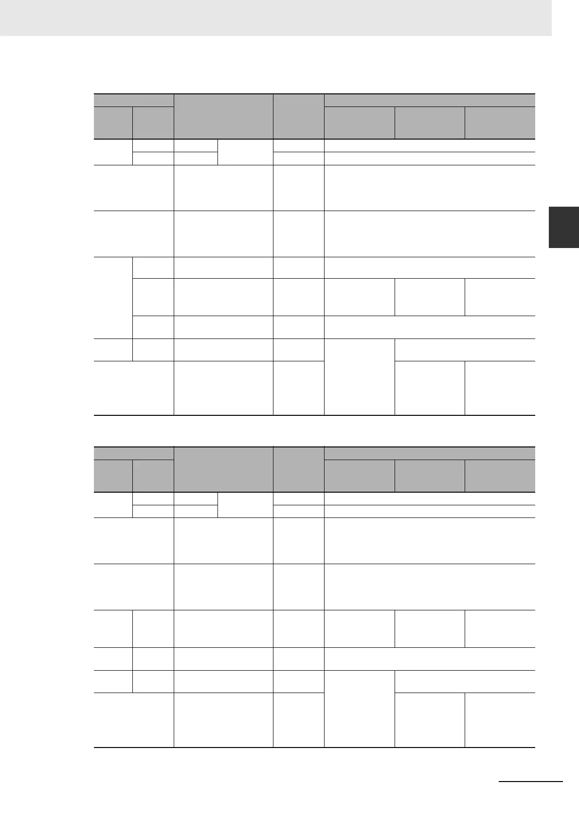
z Connections for Pulse Output 1
z Connections for Pulse Output 2 (Only for N30/40/60 CPU Units)
Terminal block
Addresses Signal
Origin search
Terminal
block
label
Terminal
number
Operating mode 0 Operating mode 1 Operating mode 2
CIO 100 01 CIO 100.01 Stored in A278
and A279
Pulse Connect to Servo Drive’s pulse input (PULS).
03 CIO 100.03 Direction Connect to Servo Drive’s direction input (SIGN).
Normal input The external signal must be
received as an input and
the input status must be
written to A541.08 in the
ladder program.
CW limit
sensor
Connect sensor to a normal input terminal.
Normal input The external signal must be
received as an input and
the input status must be
written to A541.09 in the
ladder program.
CCW limit
sensor
Connect sensor to a normal input terminal.
CIO 0 05 CIO 0.05 Origin prox-
imity input
Connect to sensor for N14 CPU Unit.
07 CIO 0.07 Origin input Connect to open-
collector output
from sensor or
other device.
Connect to the
phase-Z signal
from the Servo
Drive.
Connect to the
phase-Z signal
from the Servo
Drive.
11 CIO 0.11 Origin prox-
imity input
Connect to sensor for N20/30/40/60 CPU Unit.
CIO 100 05 CIO 100.05 Error counter
reset output
Not used. Connect to error counter reset (ECRST)
of the Servo Drive.
Normal input The external signal must be
received as an input and
the input status must be
written to A541.10 in the
ladder program.
Positioning
completed
input
Not used. Connect the Posi-
tioning Completed
Signal (INP) from
the Servo Drive to
a normal input ter-
minal.
Terminal block
Addresses Signal
Origin search
Terminal
block
label
Terminal
number
Operating mode 0 Operating mode 1 Operating mode 2
CIO 101 00 CIO 101.01 Stored in A52
and A53.
Pulse Connect to Servo Drive’s pulse input (PULS).
02 CIO 101.02 Direction Connect to Servo Drive’s direction input (SIGN).
Normal input The external signal must be
received as an input and
the input status must be
written to A542.08 in the
ladder program.
CW limit
sensor
Connect sensor to a normal input terminal.
Normal input The external signal must be
received as an input and
the input status must be
written to A542.09 in the
ladder program.
CCW limit
sensor
Connect sensor to a normal input terminal.
CIO 0 08 CIO 0.08 Origin input Connect to open-
collector output
from sensor or
other device.
Connect to the
phase-Z signal
from the Servo
Drive.
Connect to the
phase-Z signal
from the Servo
Drive.
CIO 1 00 CIO 1.00 Origin prox-
imity input
Connect to sensor
CIO 100 06 CIO 100.06 Error counter
reset output
Not used. Connect to error counter reset (ECRST)
of the Servo Drive.
Normal input The external signal must be
received as an input and
the input status must be
written to A542.10 in the
ladder program.
Positioning
completed
input
Not used. Connect the Posi-
tioning Completed
Signal (INP) from
the Servo Drive to
a normal input ter-
minal.