12 Pulse Outputs
12-14
CP2E CPU Unit Software User’s Manual(W614)
The pulse outputs are used by executing pulse control instructions in the ladder program.
z Applicable Instructions
The following instructions are used.
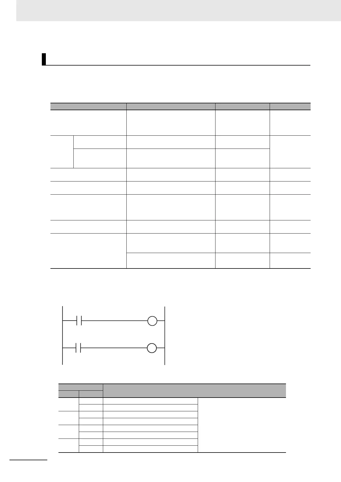
z Outputting to the Auxiliary Area Using the OUT Instruction
The OUT instruction in the ladder program is used to write signals received from the CW limit sensor
and CCW limit sensor connected to normal inputs to the Auxiliary Area bits.
Bits Written in the Auxiliary Area
Executing Pulse Control Instructions in a Ladder Program
Purpose Overview Instruction Reference
Performing trapezoidal control Performs trapezoidal pulse output
control with independent accelera-
tion and deceleration rates.
(The number of pulses can be set.)
PLS2: PULSE
OUTPUT
Refer to 12-2
Jogging Without acceleration
and deceleration
Performs pulse output control without
acceleration or deceleration.
SPED: SPEED
OUTPUT
Refer to 12-3
With acceleration
and deceleration
Performs trapezoidal pulse output
control with the same acceleration
and deceleration rates.
ACC:
ACCELERATION
CONTROL
Performing interrupt feeding Performs interrupt feeding with inter-
rupt input and pulse output.
IFEED: INTERRUPT
FEEDING
Refer to 12-4
Positioning Linear Interpolation Performs 2-axis to 4-axis linear inter-
polation.
ITPL: LINEAR
INTERPOLATION
Refer to 12-5
Performing origin searches Actually moves the motor with pulse
outputs and defines the machine ori-
gin based on the Origin Proximity
Input and Origin Input signals.
ORG: ORIGIN
SEARCH
Refer to 12-6-4
Performing origin returns Returns to the origin position from
any position.
ORG: ORIGIN
SEARCH
Refer to 12-6-6
Changing or reading the pulse
output PV
Changes the PV of the pulse output.
(This operation defines the origin
location.)
INI: MODE
CONTROL
Refer to 12-6-7
Reads the PV of the pulse output. PRV: HIGH-SPEED
COUNTER PV READ
Refer to 12-7
Auxiliary Area
Name
Word Bit
A540 08 Pulse Output 0 CW Limit Input Signal Signals must be received from exter-
nal sensors connected to normal
inputs and then written to the Auxil-
iary Area by the user program.
09 Pulse Output 0 CCW Limit Input Signal
A541 08 Pulse Output 1 CW Limit Input Signal
09 Pulse Output 1 CCW Limit Input Signal
A542
08 Pulse Output 2 CW Limit Input Signal
09 Pulse Output 2 CCW Limit Input Signal
A543
08 Pulse Output 3 CW Limit Input Signal
09 Pulse Output 3 CCW Limit Input Signal
Normal input from
CW limit sensor
CW Limit Input Signal
A540.08, A541.08,
A542.08 or A543.08
Normal input from
CCW limit sensor
CCW Limit Input Signal
A540.09, A541.09,
A542.09 or A543.09