14 Serial Communications
14-46
CP2E CPU Unit Software User’s Manual(W614)
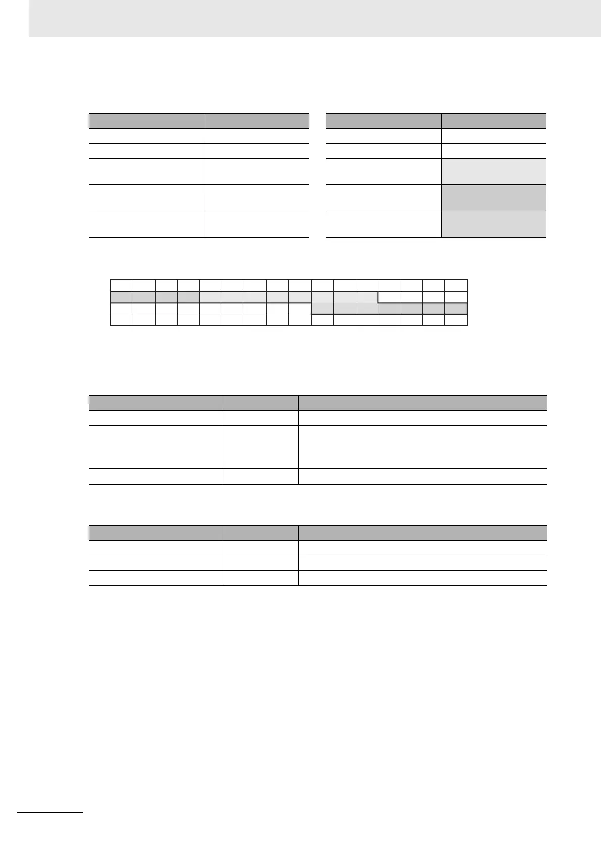
Example: Reading 19 bits from W1.04 to W2.06
Command (Modbus-RTU Master) Response (CP2E)
* The remaining bits less than one byte will be read as 0.
Note The subscript numbers in the shaded boxes indicate the ON/OFF (1/0) status of the bits that are read.
z Read Multiple Words from the Data Memory (D) (Read Holding Registers)
Command (Modbus-RTU Master)
Note The maximum number of coils depends on the assigned starting address.
Response (CP2E)
Field name Data Field name Data
Function code 01 Hex Function code 01 Hex
Coil starting address (H) 00 Hex Byte count 03 Hex
Coil starting address (L) 14 Hex
(20 bits W1.04~)
Coil status 27 to 20
CD Hex
(W1.11 to W1.04)
Quantity of coils (H) 00 Hex Coil status 35 to 28
B6 Hex
(W2.03 to W1.12)
Quantity of coils (L) 13 Hex (19 bits)
(W1.04 to W2.06)
Coil status 38 to 36
05 Hex*
(W3.06 to W3.04)
Field name Data length Data
Function code 1 byte 03 Hex
Register starting address 2 bytes E-type: 0 to 0FFF Hex (D0 to D4095)
S-type: 0 to 1FFF Hex (D0 to D8191)
N-type: 0 to 3FFF Hex (D0 to D16383)
Quantity of Registers 2 bytes 1 to 7D Hex (1 to 125)
Field name Data length Data
Function code 1 byte 03 Hex
Byte count 1 byte 2×N (N: Quantity of registers)
Register value 2×N bytes
15
14 13 12 11 10 9 8 7 6 5 4 3 2 1 0
15
14 13 12 11 10 9 8 7 6 5 4 3 2 1 0
63
62 61 60 59 58 57 56 55
47
46 45 44 43 42 41 40 39
54 53 52 51 50 49 48
31
30 29 28 27 26 25 24 23 22 21 20 19 18 17 16
38 37 36 35 34 33 32
1
01 11 1 00 101 0
001111 0
0CH
1CH
2CH
3CH