15 Ethernet
15-24
CP2E CPU Unit Software User’s Manual(W614)
This section describes the FINS commands that can be sent to PLC’s Ethernet module and the
responses to each command.
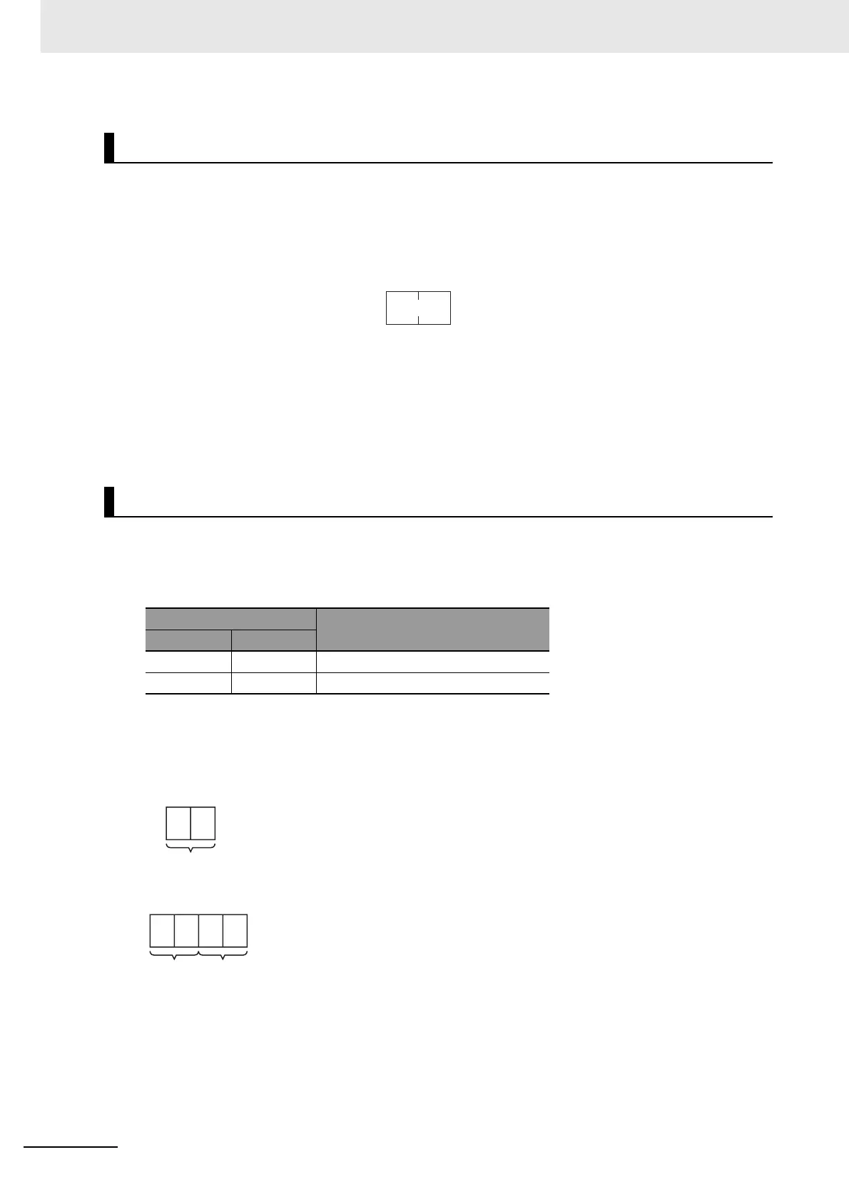
The command, response, and (where applicable) the results storage blocks are given with the com-
mands in graphic form as shown in the following diagram. If the data is fixed, it is included in the blocks.
If the data is variable, it is described following the blocks. Each box represents 1 byte; every two boxes
represents 1 word. The following diagram shows 2 bytes, or 1 word.
The results storage format is the format used to store transfer results.
Response codes applicable to the command are described at the end of the command description. If
any UNIX error codes are generated, these are also described. Refer to your UNIX error symbol defini-
tion file /usr/include/sys/errno.h for details. UNIX errors are returned in the results storage area.
Note Except for special cases, all send/receive data is in hexadecimal format.
z Command Code List
The command codes listed in the following table can be sent to the built-in Ethernet port.
The destination unit address (DA2) in FINS frame should be set as 0xFA.
z RESET: 0403
Reset the Ethernet Unit.
Command Block
Response Block
Command/Response Reference
New FINS Commands Addressed to Built-in Ethernet Port (0xFA)
Command code Name
MRC SRC
04 03 RESET
05 01 ETHERNET PORT DATA READ
Two bytes
04 03
Command code
Response
code
04 03
Command
code