17 Analog Input/Output Option Board
17-14
CP2E CPU Unit Software User’s Manual(W614)
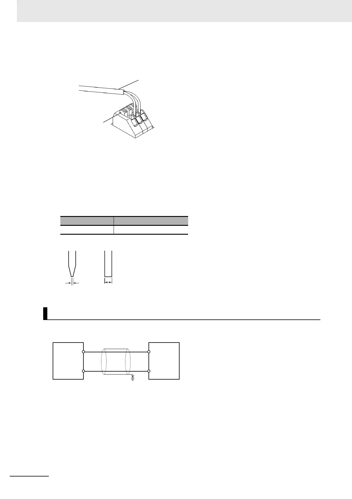
z Terminal Wiring
When wiring the analog I/O terminal block, treat either solid or stranded wires directly.
• To make the connection, press the release button in with a small flat blade screwdriver and push
the line in while the lock is released. Remove the screwdriver and lock it inside.
• To disconnect the wiring, press the release button in with a small flat blade screwdriver and pull
the line out while the lock is released.
Note 1 Ferrules without plastic sleeve cannot be used.
2 When using stranded wire, twist the core so that the barbed wires cannot protrude.
3 Do not solder-plate the end of cable.
The screwdriver shown below is recommended for wiring.
To prevent noise, 2-core shielded twisted-pair cable should be used.
Note 1 Separate wiring from power lines (AC power supply lines, high-voltage lines, etc.)
2 When there is noise in the power supply line, install a noise filter on the input section and the power supply.
3 When external power is supplied, or when the power is interrupted, there may be a pulse status analog
output of up to 1 ms. If this status is a problem, take the following measures.
• Turn ON the power to the CP2E N-type CPU Unit, check the operation status, and then turn ON the
power at the load.
• Turn OFF the power to the load and then turn OFF the power to the CP2E N-type CPU Unit.
Model Manufacturer
SZS 0.4×2.5 Phoenix Contact
Wiring for Analog Outputs
Release button
2-conductor shielded
twisted-pair cable
0.4mm
Side Front
2.5mm
COM
V OUT
Analog
output
option
board
Analog
device with
voltage
input
FG
2-core shielded
twisted-pair cable
+
−