A-77
Appendices
CP2E CPU Unit Software User’s Manual(W614)
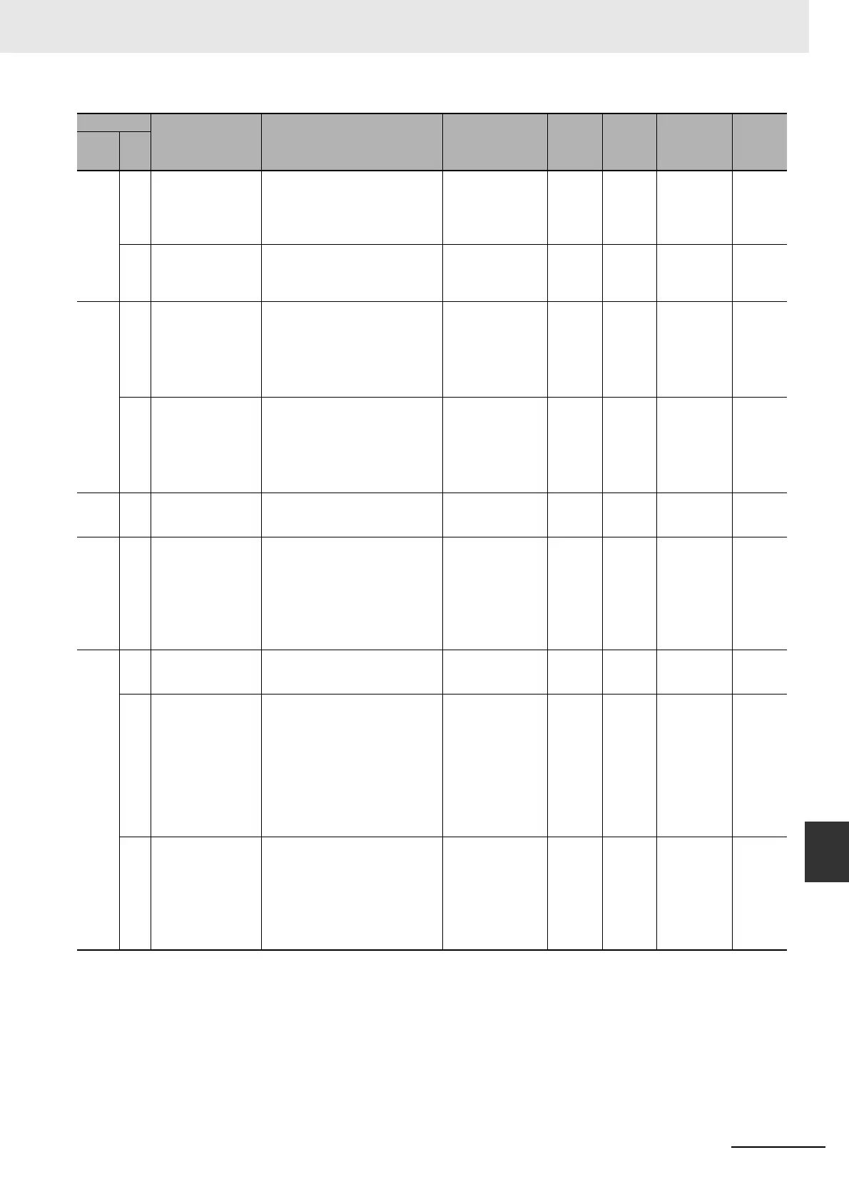
A-2 Auxiliary Area Allocations by Address
App
A-2-1 Read-only Words
A393 00 to
07
Serial Port 1/
Built-in RS-232C Port
Polled Unit
Communications Flags
The corresponding bit will be ON when
the serial port 1 or built-in RS-232C
port is communicating with NT Link
mode or Serial PLC Link mode.
Bits 0 to 7 correspond to Units 0 to 7.
ON: Communicating
OFF: Not
communicating
Retained Cleared Refreshed
when there is a
normal
response to
the token.
00 to
15
Serial Port 1/
Built-in RS-232C Port
Reception Counter
(No-protocol Mode)
Indicates (in binary) the number of
bytes of data received when the serial
port 1 or built-in RS-232C port is in
no-protocol mode.
Retained Cleared Refreshed
when data is
received.
A394 00 to
07
Serial Port 2/
Built-in RS-485 Port
Polled Unit
Communications Flags
(CP2E N30/40/60 or
S-type CPU Unit
only)
The corresponding bit will be ON when
the serial port 2 or built-in RS-485 port
is communicating with NT link mode or
Serial PLC Link made.
Bits 0 to 7 correspond to Units 0 to 7.
ON: Communicating
OFF: Not
communicating
Retained Cleared Refreshed
when there is a
normal
response to
the token.
00 to
15
Serial Port 2/
Built-in RS-485 Port
Reception Counter
(No-protocol Mode)
(CP2E N30/40/60 or
S-type CPU Unit
only)
Indicates (in binary) the number of
bytes of data received when the serial
port 2 or built-in RS-485 port is in
no-protocol mode.
Retained Cleared Refreshed
when data is
received.
A395 08 Clock Stop Flag • ON if Clock stop working.
• Cleared when Clock set.
ON: Clock stops
OFF: Clock is running
Retained Cleared Refreshed
when power is
ON.
A400 --- Error code When a non-fatal error (user-defined
FALS or system error) or a fatal error
(user-defined FALS or system error)
occurs, the 4-digit hexadecimal error
code is written to this word.
Note When two or more errors occur
simultaneously, the highest error
code will be recorded.
Cleare
d
Cleared Refreshed
when error
occurs.
A401 04 Built-in Ethernet Stop
Error Flag
ON when the built-in Ethernet stops.
The ERR/ALM indicator on front of the
CPU unit will light.
ON: Error
OFF: Normal
Retained Cleared Refreshed
when error
occurs.
06 FALS Error Flag
(fatal error)
ON when a fatal error is generated by
the FALS instruction. The CPU Unit will
stop operating and the ERR/ALM
indicator will light.
The corresponding error code will be
written to A400. Error codes C101 to
C2FF correspond to FALS numbers
001 to 511.
Note This flag will be turned OFF when
the FALS errors are cleared.
ON: FALS executed
OFF: FALS not
executed
Cleared Cleared Refreshed
when error
occurs.
A400
08 Cycle Time Too Long
Flag
(fatal error)
ON if the cycle time exceeds the
maximum cycle time set in the PLC
Setup (the cycle time monitoring time).
CPU Unit operation will stop and the
ERR/ALM indicator on the front of the
CPU Unit will light.
Note This flag will be turned OFF when
the error is cleared.
ON: Cycle time over
max.
OFF: Cycle time
under max.
Cleared Cleared Refreshed
when the cycle
time exceeds
maximum.
PLC
Setup
(Cycle
time
monitorin
g time)
Address
Name Function Settings
Status
after
mode
change
Status at
startup
Write
timing
Related
flags,
settings
Words Bits

 Loading...


