53
RFID System
Operation Manual
Section 3 Switch Settings
Section 3
Preparing Communications
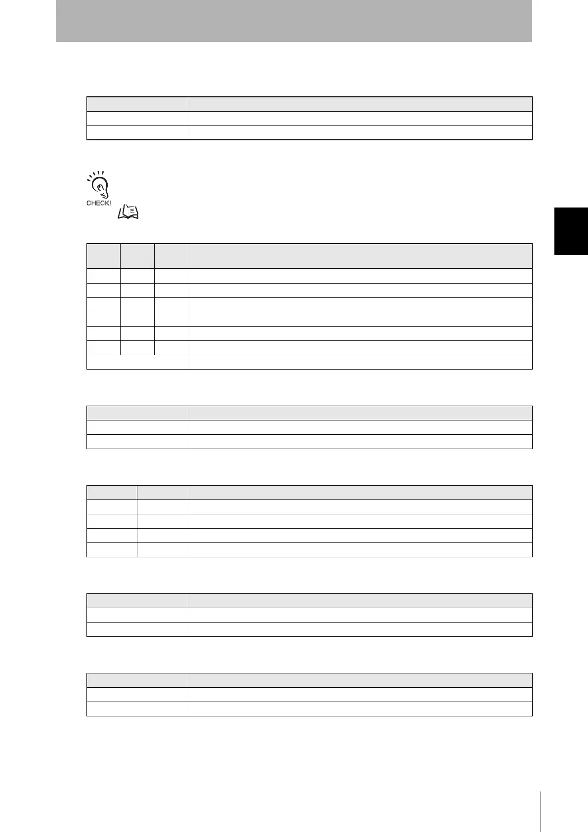
■ DIP Switches (SW3 and SW4)
■ SW3 Pin 1: DIP Switch/Internal Setting Selector
Note: Switches SW1, SW2, SW3 pins 2 to 10, and SW4 pins 1 to 4 are enabled only when SW3 pin 1 is OFF (DIP switches
enabled).
If the internal settings are enabled, settings made with the TR and SP commands are used.
The default settings will be used until they are changed with the TR and SP commands.
p.130, p.132
■ SW3 Pins 2 to 4: Baud Rate Setting
■ SW3 Pin 5: Data Length Setting
■ SW3 Pins 6 and 7: Parity Setting
■ SW3 Pin 8: Stop Bit Setting
■ SW3 Pin 9: Communications Protocol Setting
■ SW3 Pin 10: Reserved.
Do not change the setting of this pin. Leave it set to OFF.
SW3 pin 1 Description
OFF DIP switches enabled.
ON Internal settings enabled.
SW3
pin 2
SW3
pin 3
SW3
pin 4
Description
OFF OFF OFF 2400 bps
OFF OFF ON 4800 bps
OFF ON OFF 9600 bps
OFF ON ON 19200 bps
ON OFF OFF 38400 bps
ON OFF ON 1200 bps
Other 2400 bps
SW3 pin 5 Description
OFF 7 bits
ON 8 bits
SW3 pin 6 SW3 pin 7 Description
OFF OFF Even
OFF ON None
ON OFF Odd
ON ON Even
SW3 pin 8 Description
OFF 2 bits
ON 1 bit
SW3 pin 9 Description
OFF 1:1
ON 1:N

 Loading...


