34
SECTION 2
Connections and Wiring
CIDRW System
User’s Manual
SECTION 2
Installation and Connections/Wiring
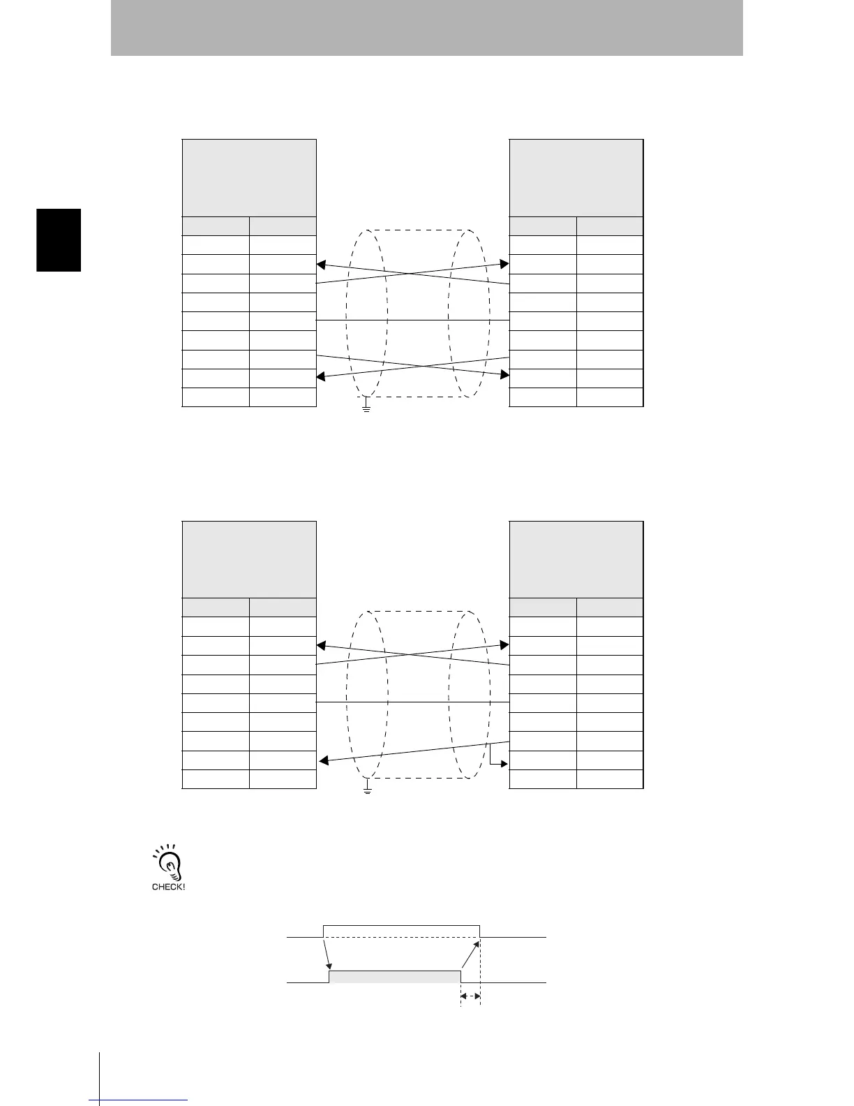
• Wiring for connection to a PC/AT computer (9-pin connector specification)
The cable length should be no greater than 15 m.
If the CS function is to be used at the PC/AT computer side, a return wire is required.
RS signal control method at the host device
In a 1:N connection, the RS signals generated from the host device by normal control must be input as CS signals. Turn
the RS signals OFF within 15 ms after the completion of data transmission. Correct communications will not be possible
without this control.
Amplifier unit
V640-HAM12
D-SUB, 9-pin
Socket type
#4-40
Name Pin No.
NC 1
RD 2
SD 3
NC 4
SG 5
NC 6
RS 7
CS 8
NC 9
PC/AT Computer
D-SUB, 9-pin
Socket type
#4-40
Pin No. Name
1NC
2RD
3SD
4NC
5SG
6NC
7RS
8CS
9NC
Ground shielded wires either at the CIDRW Controller side or at the
PC/AT side.
Amplifier unit
V640-HAM12
D-SUB, 9-pin
Socket type
#4-40
Name Pin No.
NC 1
RD 2
SD 3
NC 4
SG 5
NC 6
RS 7
CS 8
NC 9
PC/AT computer
D-SUB, 9-pin
Socket type
#4-40
Pin No. Name
1NC
2RD
3SD
4NC
5SG
6NC
7RS
8CS
9NC
Ground shielded wires either at the CIDRW Controller side or at the
PC/AT side.
SD at host device
RS at host device
ON only during data transmission from the host device
Within 15 ms