90
SECTION 5
When SECS is Used
CIDRW System
User’s Manual
SECTION 5
Troubleshooting
• When the CIDRW Controller responds to a message transmission
There is a mistake in the message sent to the CIDRW Controller or the Amplifier Unit settings. After
taking the appropriate corrective action, restart the Controller and the Amplifier Unit and send the mes-
sage again.
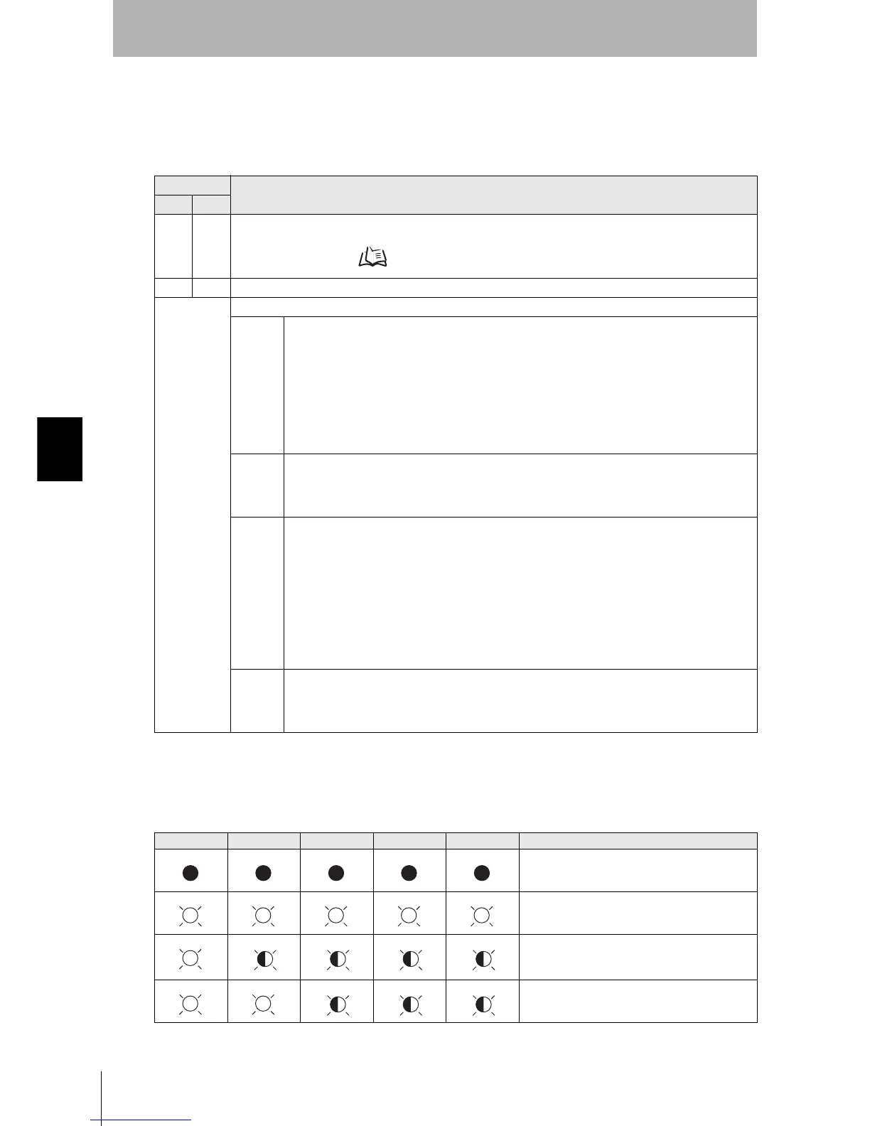
• When all the LEDs are lit or flashing
An error has occurred in the CIDRW Controller.
After taking the appropriate corrective action, restart the CIDRW Controller.
Response
Main check points
S F
— 0 Status conditions when the message was issued (e.g. a Write ID Request message (S18, F11) was sent in
the operating mode, or the message was sent during initial processing)
Operation Conditions Refer to page 76.
9 7 Message composition: illegal attributes, insufficient items, etc.
Other than
above
Ascertain the cause from the contents of the SSACK response.
CE • Mistake in the details of the items in the message
(The node number of an amplifier that is not set was specified as the TARGET ID, or a segment
name that is not set has been specified for DATASEG.)
• Connection of RS-485 cables between Amplifier Units (failure to detect Amplifier Units)
• Amplifier Unit baud rate settings (failure to detect Amplifier Units)
• Node numbers of the Amplifier Units (The same number is set for more than one unit, making
detection impossible)
• Cable routing between the host device and CIDRW Controller (influence of background noise)
• Noise levels of the power supply line to the CIDRW Controller
EE • Installation distance/inclination between the ID Tag and CIDRW Head
• Background noise levels of the CIDRW Head
• Installation spacing in relation to CIDRW Heads connected in other CIDRW systems
• When the ID read command is executed, the carrier ID contains non-visible ASCII code.
HE • Mistake in the details of the items in the message
(A segment that does not match the Amplifier Unit specifications has been set; the response
time-out setting is not correct.)
• Connection and wiring of cable between CIDRW Controller and Amplifier Unit
• Power supply to Amplifier Units
• Amplifier Unit terminal resistance settings
• Routing of each cable (influence of background noise)
• Node numbers of the Amplifier Units (the same number is set for more than one unit)
• Amplifier Unit error (hardware error)
• Noise levels of the power supply line
TE • Type/specifications of the ID Tags used
• Settings of the ID Tags used (lock, etc.)
• Environment of use of the ID Tags (ID Tag breakage due to use in unanticipated ways)
• ID Tag overwrite life
POWER OPERATING ALARMS BUSY ERROR Main check points
• Supply of 24 VDC power
• The CIDRW Controller may be damaged.
• Mode switch setting (Is the setting 0?)
If the error cannot be resolved after checking,
the CIDRW Controller may be damaged.
• The CIDRW Controller may be damaged.