10.
Install and tighten the two through capscrews.
11. Install solenoid plunger in lever. Secure solenoid to
front bracket with two machine screws.
12. Install wire lead to the terminal
“M”
on solenoid.
13.
After assembly, adjust pinion clearance. Pinion
clearance should be 0.020 to
0.080
inch
(0.5
to
2.0
mm);
if
not, check as follows. See Figure
5.
A. Connect starter to a battery (Figure
5).
Close
switch. This will shift pinion into cranking
position.
B.
Push pinion back by hand and measure pinion
clearance. If clearance does
not
fall within the
specified limits, adjust by adding or removing
shims located between solenoid and front
bracket. Adding shims decreases clearance;
removing shims increases clearance. Shims are
included with replacement solenoid.
PINION
-/
i+
PINION CLEARANCE
ES-1623
FIGURE
5.
PINION CLEARANCE ADJUSTMENT
Inspection and Testing
Inspect the starter components for mechanical defects
before testing for grounds or shorts.
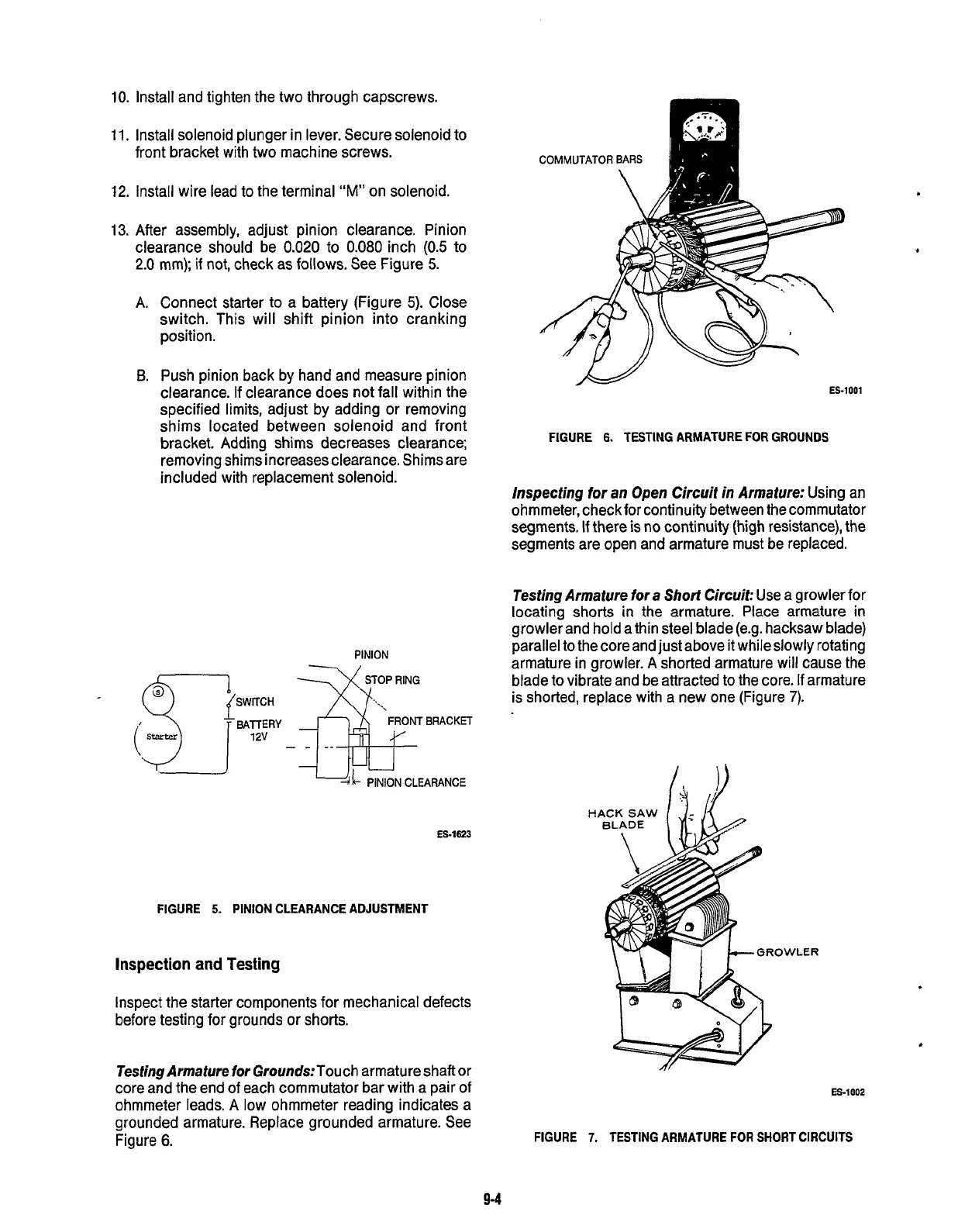
Testing Armature
for
Grounds:Touch armature shaft or
core and the end of each commutator bar with a pair
of
ohmmeter leads. A low ohmmeter reading indicates a
grounded armature. Replace grounded armature. See
Figure
6.
ES-1001
w
FIGURE
6.
TESTING ARMATURE FOR GROUNDS
hpecting
for
an
Open
Circuit
in
Armature:
Using an
ohmmeter, check for continuity between the commutator
segments.
If
there
is
no continuity (high resistance), the
segments are open and armature must be replaced.
Testing Armature
for
a
Short
Circuit:
Use a growler for
locating shorts
in
the armature. Place armature
in
growler and hold a thin steel blade(e.g. hacksaw blade)
parallel to the core and just above it whileslowly rotating
armature in growler.
A
shorted armature will cause the
blade
to
vibrate and be attracted to the core.
If
armature
is shorted, replace with a new one (Figure
7).
H
.ER
ES-1002
FIGURE
7.
TESTING ARMATURE
FOR
SHORT CIRCUITS
9-4
Redistribution or publication of this document,
by any means, is strictly prohibited.
 Loading...

