FLYWHEEL
GEAR
COVER
Removing the flywheel isa relatively simple process, but
the following procedure must be followed to avoid
damage to the gear case and possible injury to the
operator.
1.
Turn the flywheel mounting screw outward about
two turns.
pAEI
Incorrect flywheel removal can
result in severe personal injury.
Do
not remove flywheel screw completely when
using flywheel puller.
2.
Install a puller bar on the flywheel as shown in
Figure
8.
FLYWHEEL
MOUNTING
SCREW
U
cs-lo00
FIGURE
8.
BLOWER WHEEL PULLEY
3.
Turn the puller bar bolts in, alternately, until the
wheel snaps loose on the shaft.
-1
Improper flywheel removal can
cause gear case damage.
Do
not
use any
tools
to pry against gear cover when
removing iiywheel.
4.
Unscrew the puller from the flywheel, remove the
flywheel mounting screw and washer and pull the
flywheel
off
the
shaft.
Take care not to drop the
wheel.
A
bent
or
broken fin will destroy the balance.
Always use a steel key for mounting the flywheel.
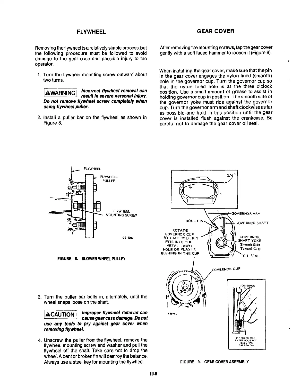
After removing the mounting screws, tap the gear cover
gently with a
soft
faced hammer to loosen it (Figure
9).
When installing the gear cover, make sure that the pin
in the gear cover engages the nylon lined (smooth)
hole in the governor cup. Turn the governor cup
so
that the nylon lined hole is at the three o’clock
position. Use a small amount of grease to assist in
holding governor cup in position. The smooth side of
the governor yoke must ride against the governor
cup. Turn the governor arm and shaft clockwise as far
as possible-and hold in this position until the gear
cover is installed flush against the crankcase. Be
careful not to damage the gear cover oil seal.
c
\+GOVERNOR
ARM
ROLL PIN
ROTATE
FITS INTO THE
/,I
I
GOVERNOR
SHAFT YOKE
(Smooth Side
Toward Cup)
GOVERNOR CUP
SO
THAT ROLL PIN’
METAL LINED
HOLE
OR
PLASTIC
EUSH~G
IN
THE
CUP
I
UI
L
aEAL
IF FEELER WILL
ENTER HOLE
112”
BALL HAS
FALLEN OUT
FIGURE
9.
GEAR
COVER
ASSEMBLY
10-6
Redistribution or publication of this document,
by any means, is strictly prohibited.
 Loading...

