Use the PNP configuration if the Mini I/O board is PNP Transistor type or
the Mini I/O board is Relay type and configured as PNP type.
Use the NPN configuration if the Mini I/O board is NPN Transistor type or
the Mini I/O board is Relay type and configured as NPN type.
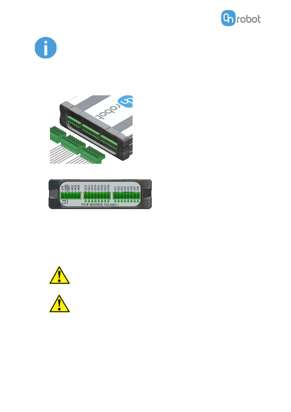
Plug in the supplied green pluggable connectors.
The supplied connector types are:
2 x Phoenix Contact MC 1,5/8-ST-3,5 Terminal Block
1 x Phoenix Contact MC 1,5/6-ST-3,5 Terminal Block
Wire the digital I/O wires from the Compute Box to the robot.
DO1-8: Digital outputs of the Compute Box (signals from the grippers/sensor to the robot)
DI1-8: Digital inputs of the Compute Box (signals from the robot to the grippers/sensor)
GND: To be used to have a common ground between the robot and the gripper/sensor
It is recommended to connect all 8 inputs and 8 outputs for simplicity.
If some of the DO1-8 or DI1-8 wires will not be connected, make sure to
unscrew it from the terminal block to avoid an accidental short circuit.
The 24V and GND pins are only Reference Voltage Output. It cannot be
used to power any equipment.
It is recommended to use the supplied wires only. If it is necessary to use
different wire, use one that is shorter than 3 m.
Connect the Compute Box inputs to the robot outputs and the Compute Box outputs to robot
inputs.
For simplicity, it is recommended to map the pins in order:
 Loading...