4. HW Installation
4.1. Overview
For a successful installation the following steps will be required:
•
Mount the components
•
Setup the software
In the following sections, these installation steps will be described.
4.2. Robot Mount
1. Mount the robot-specific adapter (if applicable)
2. Mount any optional accessories
3. Mount the Quick Changer option
4. Mount the tool(s) (if applicable)
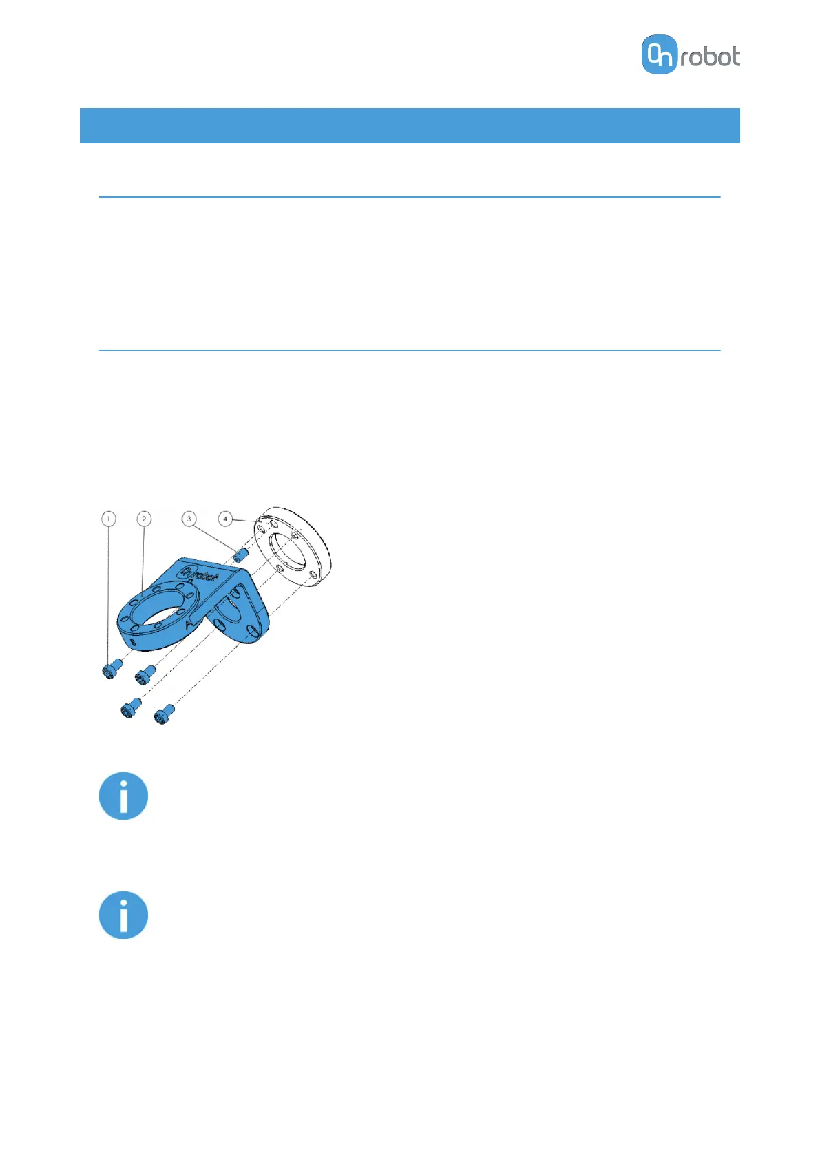
4.2.1. Optional - Angle Bracket
Angle Bracket
1. M6x10 screws (ISO14580 8.8)
2. Angle Bracket (ISO 9409-1-50-4-M6)
3. Dowel pin Ø6x10 (ISO2338 h8)
4. Adapter/Robot tool flange (ISO
9409-1-31.5-4-M5)
Use 10 Nm tightening torque.
NOTE:
If using the optional Angle Bracket, make sure to always adjust the TCP as
described in the 8.3.2. COG, TCP section. Otherwise some of the functionality
may not work properly.
NOTE:
With Angle Bracket the HEX-E/H QC and the Dual QC is not supported.
HW INSTALLATION
11


 To Next Page