VG10 User Manual 1.1.0
Page 12 of 40
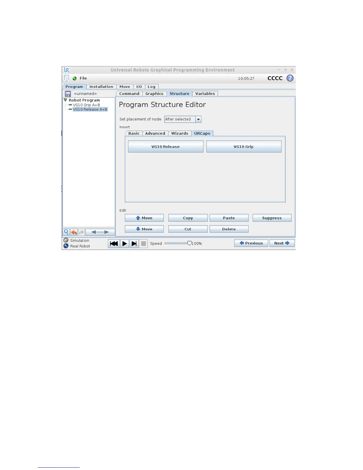
Structures
The structure tab is used to insert the Grip and Release function in the Robot program
structure tree (See figure 2.2 below). At the URCaps tab you will find the two buttons.
VG10 Grip
This structure is used to activate the pump and generate vacuum (see figure 2.3). It is
possible to select channel A, B or both (See stickers under the VG10 arms to see which
arms channel A is and which is channel B). The higher vacuum percentage the more
lifting power.
The VG10 URCap keeps track of total payload, when using the VG10 Grip and VG10
Release nodes along with the tool weight in the installation node to manage payload
settings. If, for instance, the tool weight is set to 1.7 kg in the VG10 Installation tab
and a payload of 2 kg is picked up on Channel A, using the VG10 Grip node, the total
payload is automatically set to 1.7 + 2 = 3.7 kg. If picking up an additional payload of 4
kg on Channel B, the total payload is automatically set to 1.7 + 2 + 4 = 7.7 kg. Likewise,
payload is removed per channel. If, in the above example, the workpiece on channel A
is removed using the VG10 Release structure, the total payload is automatically
adjusted to 1.7 + 4 = 5.7 kg.
The setting “wait for proper grip” means that the program will stay in the VG10 Grip
structure until commanded vacuum is achieved. The setting “Stop robot on
subsequent lost grip” means that the vacuum is monitored continuously and if the
vacuum disappears unexpectedly the robot will stop with a popup.