VG10 User Manual 1.1.0
Page 24 of 40
Vacuum
Vacuum is defined as the percentage of absolute vacuum achieved relative to
atmospheric pressure, i.e.:
The vacuum percentage setting is the target vacuum. The pump will run at full speed
until the target vacuum is achieved, and then run at a lower speed necessary to
maintain the target vacuum.
The pressure in the atmosphere varies with weather, temperature and altitude. The
VG10 automatically compensates for altitudes up to 2km, where the pressure is about
80% of sea level.
Air flow
Air flow is the amount of air that must be pumped to maintain the target vacuum. A
completely tight system will not have any air flow, whereas real life applications have
some smaller air leakages from two different sources:
• Leaking vacuum cup lips
• Leaking workpieces
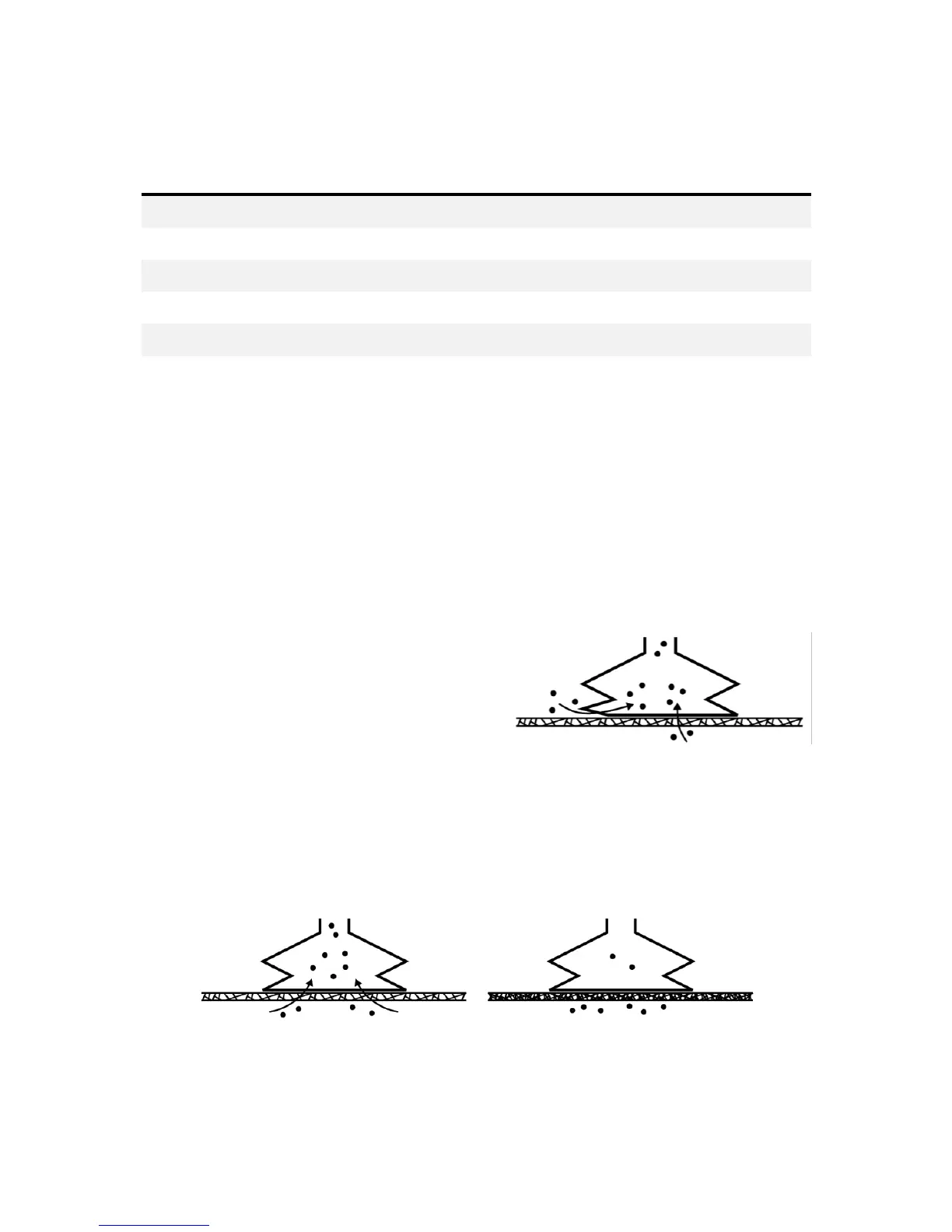
The smallest leak under a vacuum cup can be
hard to find (see figure 3.5). Choosing the
right vacuum cups are essential, (Table:
Choosing a vacuum cup type).
Leaking workpieces can be even harder to identify. Things that look completely tight
might not be tight at all. A typical example is coarse cardboard boxes. The thin outer
layer is often requiring a lot of air flow to create a pressure difference over it (see
figure 3.6 below).