VG10 User Manual 1.1.0
Page 28 of 40
Electrical characteristics
The VG10 supports a wide range of control methods, making it suitable for all of the
following:
• Universal Robots – URCap, scripts and manual I/O control
• Other robots – Manual 24 V I/O control and MODBUS RTU (RS485) commands
• PLC – Manual 24 V I/O control and MODBUS RTU (RS485) commands
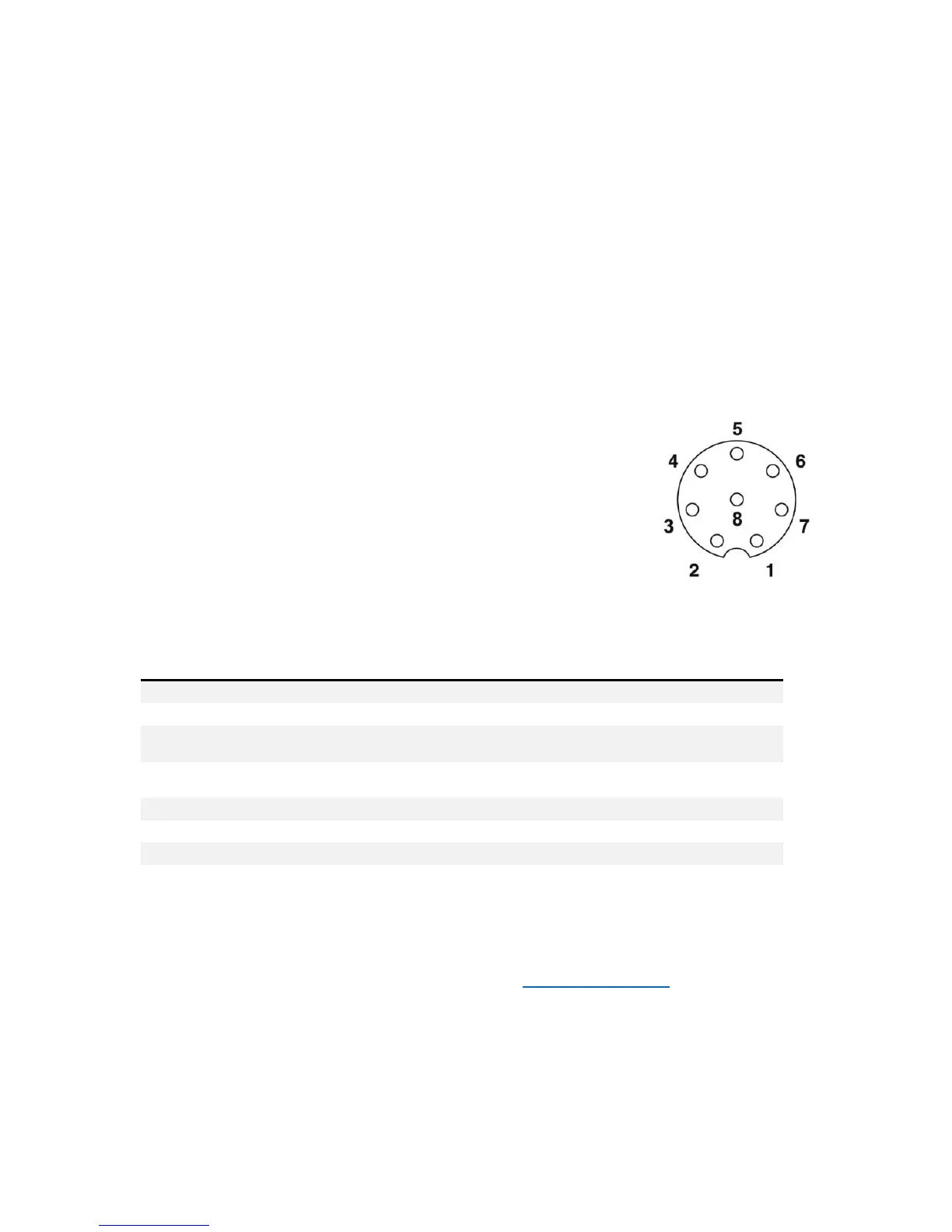
The connector on the VG10 is an 8-way, coding A, gold contacts as defined in IEC
61076-2-104. The following cables are compliant and recommended:
• OnRobot A/S, 200 mm male-female, PN 10071
• Phoenix contact, 200 mm male-female, PN 1416505
• Phoenix contact, 10 meter open ended PN 1404183
The 24V I/O signals in the VG10 control cable are constructed for
reliable communication with robots and PLC’s conforming to IEC
61131-2. Below is an overview of the signals and their respective
functions:
By default, the VG10 support basic manual control through simple 24V PLC I/Os, see
manual control on page 17. OnRobot A/S continuously improve guidance and features
for different robot manufacturers; find more on www.onrobot.com.