Intersection Equipment Installation Instructions
15
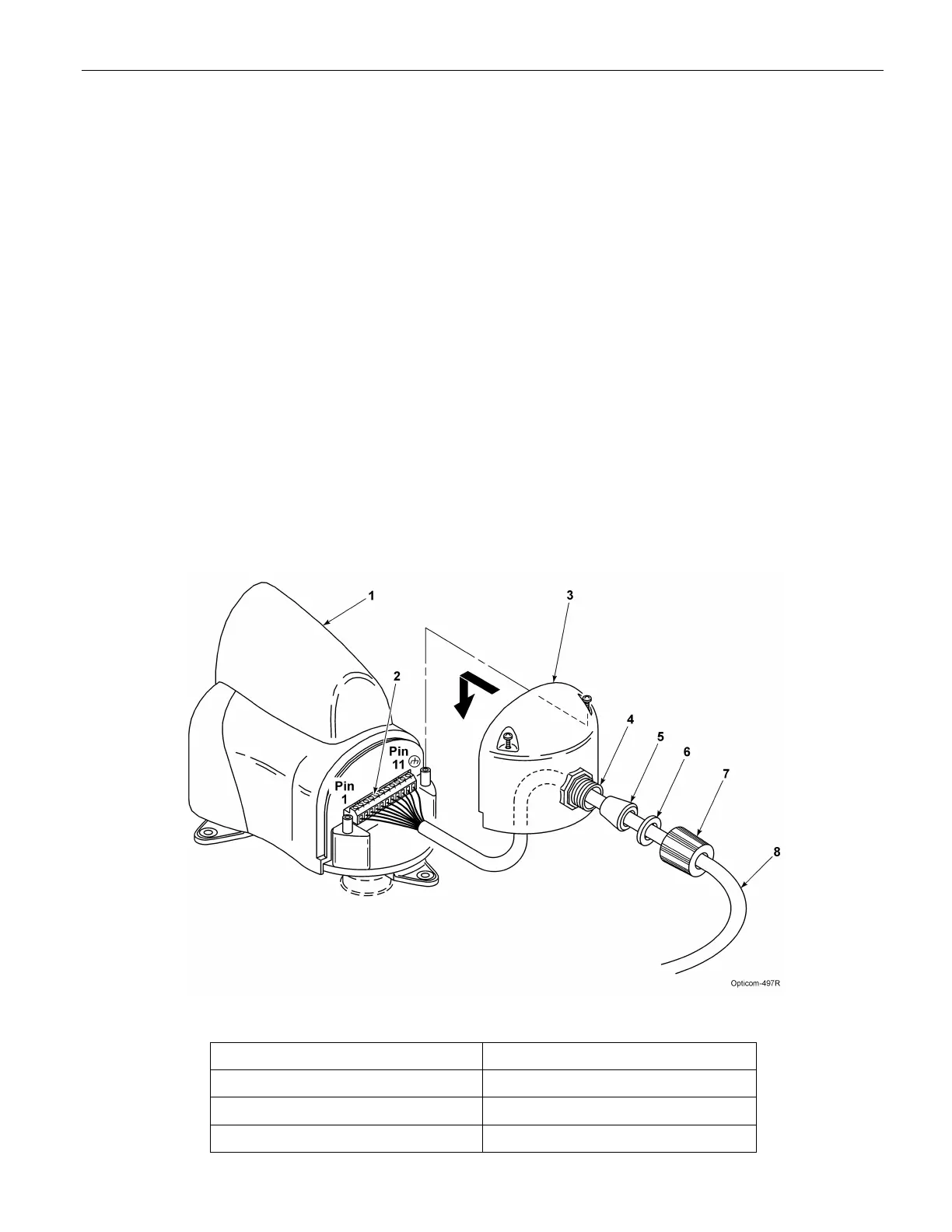
1. Disassemble the weather-tight cable retainer and route the cable through the compression nut,
plastic washer, rubber bushing, and into the cover as shown in Figure 3-6. Leave approximately 4
inches (10 cm) of cable inside the cover and tighten the compression nut to secure the cable.
2. Strip approximately 3 inches (8 cm) of the outer jacket from the end of the cable. Be careful not to
cut the wires inside. Make sure the outer jacket is held in place by the rubber bushing.
3. Strip 1/4 in (6 mm) of insulation from each wire.
NOTE:
It is very important to not strip too much insulation, as it may lead to short circuits, or too little
insulation, as it may prevent the wire from making good contact.
4. Place each wire into the appropriate hole in the 11-pin terminal block and tighten the screw to
secure the wire. The label on the terminal block shows the color of each wire. Table 3-1 also
shows the terminal block pin number, wire color, and function of each wire.
5. The terminal block may be removed to allow easier connections.
6. Replace the wiring cover and tighten the screws.
7. Orient the radio/GPS unit so that the cable retainer is facing an area from which vehicles will NOT
be approaching.
8. Tighten the locknuts on the nipple/pipe to secure the radio/GPS unit so it will not move.
9. Finish routing and securing the cable. Use cable ties as required. Keep the cable lower than the
entry point or use a drip loop.
Figure 3-6. Model 1010 Radio/GPS Cable Installation
1. Intersection radio/GPS unit 5. Rubber bushing
2. 11-pin terminal block 6. Plastic washer
3. Wiring cover 7. Compression nut
4. Cable retainer 8. Radio/GPS cable