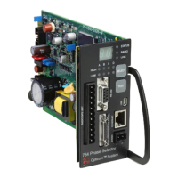
EasyManua.ls Logo

OPTICOM 764 User Manual

OPTICOM 764
73 pages
To Next Page IconTo Next Page
Page #1 background imageLoading...
Page #1 background image
Opticom
GPS System
Intersection Equipment
Opticom
GPS System
Opticom
IR System
Model 764 Phase Selector
Installation Manual November 2012

Table of Contents

Question and Answer IconNeed help?

Do you have a question about the OPTICOM 764 and is the answer not in the manual?

OPTICOM 764 Specifications

General IconGeneral
BrandOPTICOM
Model764
CategoryRecording Equipment
LanguageEnglish

Summary

1 About This Manual

Intended Use

Describes the system's intended application for priority vehicles.

Technical Support

Provides contact information for technical assistance with the system.

Safety Messages and Labels

Highlights the importance of safety messages and labels within the manual.

Safety Considerations

Outlines important safety precautions to follow before installation.

Electric Shock Precautions

Details risks and safety measures related to electrical shock during installation.

Disposal of Device

Instructs on the proper disposal of the device according to regulations.

FCC Statement

Provides information on FCC compliance and potential interference.

2 Description

Opticom GPS System Overview

General description of the Opticom GPS system and its purpose.

Intersection Equipment Components

Lists and describes the components of the intersection equipment.

System Operation Description

Explains how the Opticom GPS system operates to manage traffic signals.

Intersection Equipment Details

Details the specific components of the intersection equipment like Radio/GPS units.

3 Radio/GPS Unit Installation

Model 1010 Radio/GPS Unit Mounting Location Considerations

Guidelines for selecting an optimal mounting location for the Model 1010 unit.

Model 1010 Radio/GPS Unit Installation

Step-by-step instructions for installing the Model 1010 unit.

Model 1010 Radio/GPS Cable Installation

Procedures for connecting and routing the radio/GPS cable for the Model 1010.

Model 1012 Radio Installation

Details on installing the Model 1012 radio unit and its considerations.

Model 1050 Antenna Mounting

Instructions for mounting the Model 1050 GPS antenna on a cabinet roof.

Model 1012 Radio Mounting

Describes how to mount the Model 1012 radio unit within a traffic cabinet.

Radio/GPS Unit Cable Terminations

Covers connecting the cables to the radio/GPS unit for the Model 1012.

4 Powering the Phase Selector

Phase Selector Power Input Specifications

Details the power input requirements and current draw for the phase selector.

Powering on 120 VAC 60 Hz

Instructions for powering the phase selector using 120 VAC.

Powering on 24VDC

Instructions for powering the phase selector using 24 VDC.

5 Phase Selector Installation in Controller Cabinets with Existing Card Racks

Cabinet Types and Input Files

Describes cabinet types and input file slots for phase selector installation.

Output Connections to Controller

Guidance on connecting phase selector outputs to traffic controller preemption inputs.

Phase Selector Installation Procedure

Step-by-step instructions for installing the phase selector into a slot.

Potential for Electrical Shock

Addresses shock hazards and verifies earth ground connections for safety.

6 Phase Selector Installation in NEMA Cabinets using 760 or 1040 Card Rack

Card Rack Requirements for NEMA Cabinets

Details card rack types needed for NEMA cabinets.

Wiring and Output Connections in NEMA Cabinets

Explains wiring and output connections for NEMA installations.

9-Pin Harness Wiring for 760 and 1040 Card Racks

Describes the wiring for the 9-pin harness used with 760/1040 card racks.

Model 1045B Card Rack Usage and Power

Explains the usage and power input for the Model 1045B card rack.

Model 1045 in IR Operation

Notes on using the Model 1045 card rack for IR operation.

7 Model 755 Four Channel Adapter Card and Other Model Card Racks

Adapter Card Installation Procedure

Steps for installing the Model 755 adapter card with phase selectors.

8 Radio/GPS Cable Connection

Connecting Radio/GPS Cable to Phase Selector

Instructions for connecting the radio/GPS cable to the phase selector terminal block.

9 Model 768 Auxiliary Interface Panel (AIP)

AIP Functions and Requirements

Lists the functions and requirements for using the AIP.

Auxiliary Interface Panel Installation

Steps for mounting and connecting the auxiliary interface panel.

Green Sense Wiring Procedures

Details on wiring green sense inputs to the AIP.

Confirmation Light Wiring with Load Switch Interface

Procedures for wiring confirmation lights using load switches.

Confirmation Light Wiring with Electromechanical Relay Interface

How to wire confirmation lights using electromechanical relays.

Connecting Existing Harnesses to Model 768 AIP

Guidelines for upgrading from older auxiliary interface panels.

Additional Output Connections via AIP

Instructions for making additional output connections using the AIP.

Logic Common Connection Requirement for AIP Outputs

Explains the necessity of connecting Logic Common for AIP outputs.

Turn Signal Dependant Operation Example

Example of configuring outputs for turn signal dependent operation.

Time Sync Output Functionality

How to enable and use the time synchronization output feature.

Output Inhibit Functionality

Instructions for using the output inhibit feature to shut off outputs.

Infrared (IR) Operation Reference

Refers to other manuals for IR detector installation details.

11 Phase Selector Pin Index

Radio/GPS Connector Pin Index

Index of pins for the 11-pin radio/GPS connector.

DC Input Connector Pin Index

Index of pins for the DC input connector.

12 Communication Ports

Ethernet Port Details

Information on the Ethernet port, including default IP and port settings.

Ethernet Port Pin Assignment

Details the pin configuration for the Ethernet port.

Ethernet Port Indicator Meaning

Explains the meaning of the Ethernet port's indicator lights.

USB Port Functionality

Details on using the USB port for communication with the phase selector.

USB Port Pin Assignments

Lists the pin assignments for the USB port.

RS-232 Communication Ports Overview

Lists the available RS-232 ports and their requirements.

Rear Edge RS-232 Port Configuration

How to enable the RS-232 communication port on the rear edge connector.

Auxiliary Interface Panel RS-232 Ports

Details on COM 3 and COM 4 RS-232 ports on the AIP.

13 Phase Selector Indicators, Display and Switches

Phase Selector Indicators

Describes the status, radio, link, and channel indicators on the phase selector.

Phase Selector Display and Switches Overview

Overview of the two-digit display and select/test switches.

Select Switch Functionality

Explains the operation of the Select switch for navigating menus.

Test Initiate Switch Functionality

Describes the function of the Test Initiate switch.

Manual Test Calls

Procedures for placing manual test calls for preemption and TSP.

Turn Signal Sub Menu Usage

How to use the turn signal sub menu for specific output activation.

Error Listing and Codes

How to view and interpret error codes displayed by the phase selector.

Set Range Functionality

Procedures for resetting range timeouts and setting detection range.

Detector Function Test

How to test infrared detector connectivity.

IP Address Reset Procedure

Steps to reset the phase selector's IP address to factory defaults.

Password Override Function

How to override a lost password for the phase selector.

Erase Logs Functionality

Procedure for erasing all system logs on the phase selector.

Reset All Parameters to Default

How to reset all configurable parameters to factory defaults.

Standby Mode Operation

How to put the phase selector into standby mode and return to normal operation.

14 Checkout

Checkout and Testing Procedures

Refers to on-site software help files for checkout and testing details.

15 Troubleshooting

Fuse Locations on Phase Selector

Identifies the location and specifications of fuses on the phase selector.

Troubleshooting Symptoms and Solutions

Provides a table of common symptoms, causes, and solutions for system issues.

16 Maintenance

Recommended Maintenance Procedures

Outlines recommended inspection and testing intervals for system components.

17 Setup and Testing

GPS/IR Mode Setup and Mapping

Instructions for setting up and mapping the phase selector for GPS/IR modes.

Appendix A: Opticom Output Connection Worksheet (High Priority only)

Worksheet for High Priority Output Connections

A worksheet to document output connections for high priority calls.

Appendix A1: Opticom Output Connection Worksheet (High & Low Priority)

Worksheet for High & Low Priority Output Connections

A worksheet to document output connections for high and low priority calls.

Appendix B: Driving a Relay from a Phase Selector

Driving Relays with Phase Selector Output

Explains how to drive relays using phase selector outputs, with precautions.

Appendix C Gate Opener Card Rack

Gate Opener Card Rack Features

Describes the features of the Model 770 and 1045 Gate Opener Card Racks.

Contact and General Use Ratings

Lists the contact and general use electrical ratings for the card racks.

Gate Opener Card Rack Installation

Step-by-step guide for installing the gate opener card rack.

Gate Opener Relay Outputs

Instructions for connecting the gate opener relay outputs.