Intersection Equipment Installation Instructions
42
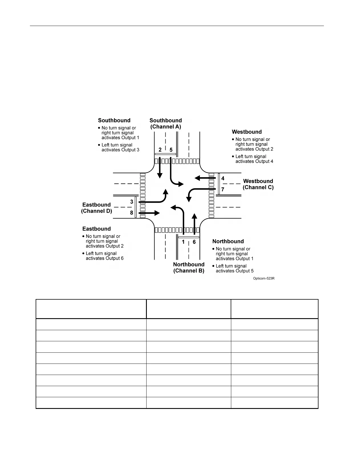
9.5.1 Turn Signal Dependant Operation Example
Figure 9-6 shows an example of an intersection with eight phases numbered 1 through 8. Table 9-4 lists the
phase selector outputs to connect to the controller preempt inputs. The table also lists which phases to
display.
For example, a northbound priority vehicle signaling for a left turn activates Output 5, which displays green
for phases 1 and 6. All other phases are red.
Figure 9-6. Eight Phase Intersection
Connect Phase Selector Output To Controller Preempt Input Then, Program Controller to
Display Greens for:
Output 1 (Rear output 1 gray/white) Input 1 Phases 2 and 6
Output 2 (Rear output 2 blue/white) Input 2 Phases 4 and 8
Output 3 (Rear output 3 violet/white) Input 3 Phases 2 and 5
Output 4 (Rear output 4 brown/white) Input 4 Phases 4 and 7
Output 5 (AIP output 1) Input 5 Phases 1 and 6
Output 6 (AIP output 2) Input 6 Phases 3 and 8
Logic Common (gray/black) Logic Common
AIP Opto Common Logic Common
Table 9-4. Turn Signal Dependant Operation Output Connection/Programming Example