Intersection Equipment Installation Instructions
46
12 Communication Ports
Phase selectors have multiple communication ports:
• One Ethernet port
• One USB port
• Four RS-232 ports
12.1 Ethernet Port
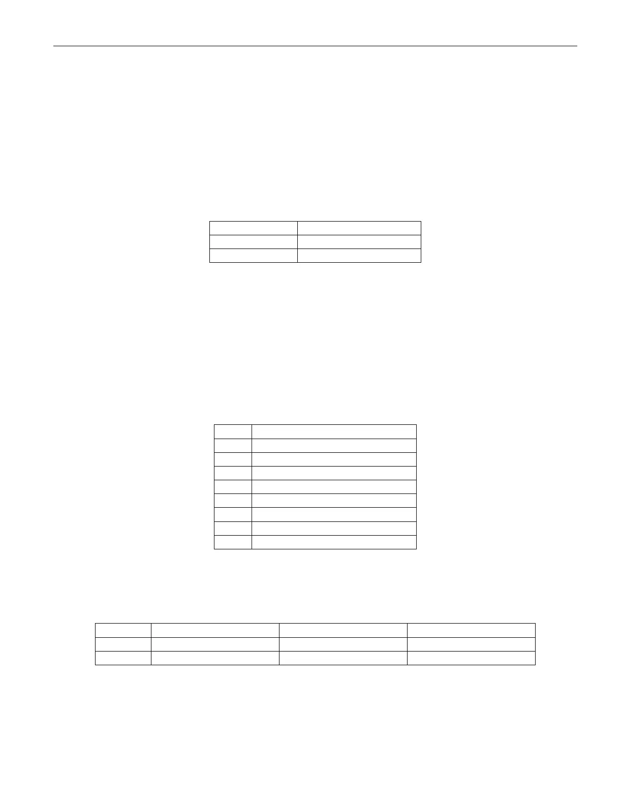
The default address for the Ethernet port is:
Table 12-1 Ethernet Port Default settings
• The address and port numbers in the phase selector may be changed using the On-site or CMS
software. See the On-site and CMS help files for details.
o Record the new address and port numbers so that you can communicate with the phase
selector.
o It is possible to reset the IP settings, see section 13-2 for details.
• Connect a standard Ethernet cable between the Ethernet port on the phase selector and the Ethernet
network device that you will use to communicate with the phase selector.
Signal Common (0V) for data 1
Signal Common (0V) for data 1
Table 12-2 Ethernet port pin assignment
12.1.1 Ethernet indicators
There are two indicator lights on the Ethernet port. The following is the meaning of these indicators:
Table 12-3 Ethernet port indicator meaning