Intersection Equipment Installation Instructions
45
Channel A primary detector input (not used in GPS only mode)
Detector 24 VDC power output (not used in GPS only mode)
Channel A output, collector (+)
Channel A output, emitter (–)
Channel B primary detector input (not used in GPS only mode)
Detector ground (not used in GPS only mode)
Channel C primary detector input (not used in GPS only mode)
Detector 24 VDC power output (not used in GPS only mode)
Channel C output, collector (+)
Channel C output, emitter (–)
Channel D primary detector input (not used in GPS only mode)
Detector ground (not used in GPS only mode)
Channel B output, collector (+)
Channel B output, emitter (–)
Channel D output, collector (+)
Channel D output, emitter (–)
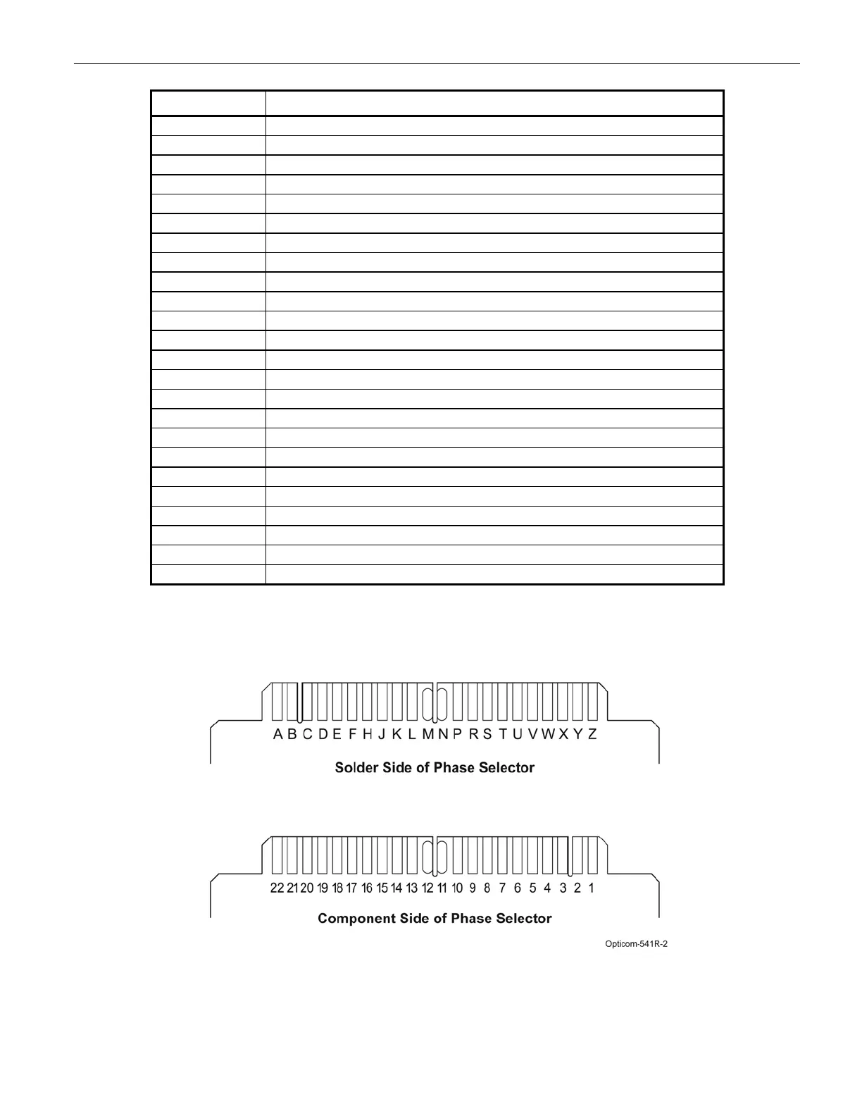
Table 11-2 Phase Selector Edge Connector Pin Index
Figure 11-1 Phase Selector Edge Connector Pin Letters and Numbers