Intersection Equipment Installation Instructions
29
8 Radio/GPS Cable Connection
1. Remove the radio/GPS cable to the terminal block on the front of the phase selector.
2. Strip approximately 3 inches (8 cm)) of the outer jacket from the end of the cable. Be careful not to
cut the wires inside.
3. Strip 1/4 inch (6 mm) of insulation from each wire.
Note:
It is very important to not strip too much insulation, which may lead to short circuits; or too little
insulation, which may prevent the wire from making good contact.
4. Place each wire into the appropriate terminal in the 11-pin terminal block and tighten the screw to
secure the wire. The label on the terminal block shows the color of each wire. Table 3-1 also
shows the terminal block pin number, wire color, and function of each wire.
a. The terminal block may be removed from the phase selector to allow easier connections.
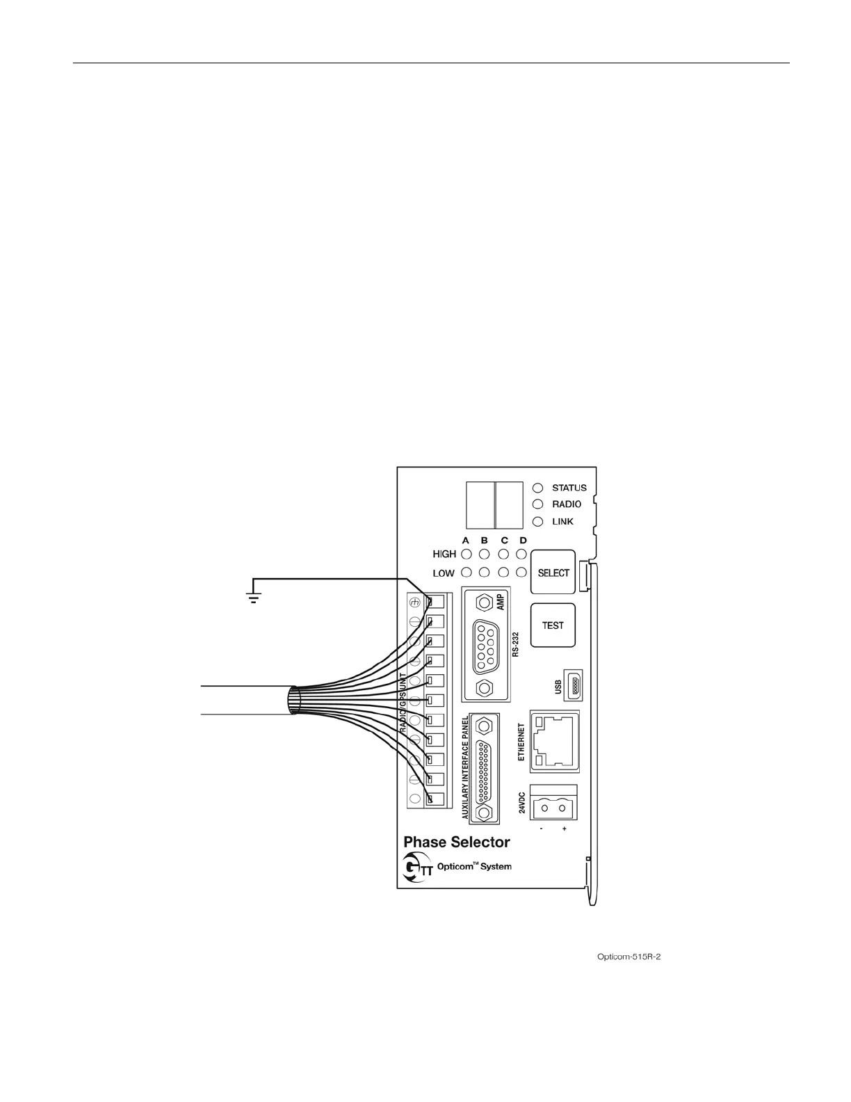
5. Connect the bare wire to pin 11 of the terminal block. Connect a user-supplied 22 to 16 AWG wire
from pin 11 to the earth ground point in the traffic control cabinet. See Figure 8-1.
Figure 8-1. Radio/GPS Cable Connection to Phase Selector