Intersection Equipment Installation Instructions
3
Table of Contents
1 About This Manual ........................................................................................................................... 5
1.1 Intended Use ............................................................................................................................. 5
1.2 Technical Support ...................................................................................................................... 5
1.3 Safety Messages and Safety Labels .............................................................................................. 5
1.4 Safety Considerations ................................................................................................................. 5
1.4.1 Personal Safety Equipment and Clothing .............................................................................. 5
1.4.2 Work Zone Traffic Control ................................................................................................... 5
1.4.3 Electric Shock ...................................................................................................................... 6
1.5 Disposal of Device ..................................................................................................................... 6
1.6 FCC Statement ........................................................................................................................... 6
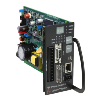
2 Description ...................................................................................................................................... 7
3 Radio/GPS unit Installation ............................................................................................................ 10
3.1 Model 1010 Radio/GPS unit mounting Location Considerations ................................................ 10
3.1.1 Model 1010 Radio/GPS Unit Installation ............................................................................ 14
3.1.2 Model 1012 Radio Installation ........................................................................................... 16
3.1.2.1 Model 1050 Antenna mounting ................................................................................... 17
3.1.2.2 Radio mounting .......................................................................................................... 18
3.1.2.3 Radio/GPS Unit Cable Terminations ............................................................................ 18
4 Powering the Phase Selector .......................................................................................................... 20
4.1 Powering on 120 VAC 60 Hz ................................................................................................... 20
4.2 Powering on 24VDC ................................................................................................................ 20
5 Phase Selector Installation in Controller Cabinets with Existing Card Racks ................................... 21
5.1 Potential for Electrical Shock .................................................................................................... 23
6 Phase Selector Installation in NEMA Cabinets using 760 or 1040 Card Rack .................................. 24
6.1 Model 1045B Card Rack .......................................................................................................... 27
6.1.1 Model 1045 in IR Operation .............................................................................................. 27
7 Model 755 Four Channel Adapter Card and Other Model Card Racks ............................................ 28
8 Radio/GPS Cable Connection ........................................................................................................ 29
9 Model 768 Auxiliary Interface Panel (AIP) ..................................................................................... 30
9.1 Auxiliary Interface Panel Installation......................................................................................... 31
9.2 Green Sense Wiring ................................................................................................................. 33
9.3 Confirmation Light Wiring ........................................................................................................ 34
9.3.1 Confirmation Light Wiring with Load Switch Interface ........................................................ 34
9.3.2 Confirmation Light Wiring with Electromechanical Relay Interface ..................................... 36
9.4 Connecting existing harnesses to the model 768 auxiliary interface panel ................................. 38
9.4.1 Existing GPS installation using model 1035 auxiliary harness ............................................. 38
9.4.2 Existing GPS installation using model 1030 auxiliary interface panel .................................. 38
9.4.3 Existing IR installation using a model 757 auxiliary harness ................................................ 38
9.4.4 Existing IR installation using a model 758 auxiliary interface panel ..................................... 38
9.5 Additional Output Connections ................................................................................................ 39
9.5.1 Turn Signal Dependant Operation Example........................................................................ 42
10 Infrared (IR) Operation ............................................................................................................... 43
11 Phase Selector Pin Index ............................................................................................................. 44
12 Communication Ports ................................................................................................................. 46
12.1 Ethernet Port ............................................................................................................................ 46
12.1.1 Ethernet indicators .......................................................................................................... 46
12.2 USB Port .................................................................................................................................. 47
12.3 RS-232 Communication Ports................................................................................................... 47