Intersection Equipment Installation Instructions
17
3.1.2.1 Model 1050 Antenna mounting
NOTES:
• Do not paint the radio/GPS antenna cover. Metals or metal oxides in the paint may interfere with
GPS reception and/or radio reception and transmission.
• Be sure to capture metal shavings when drilling a hole in the cabinet.
Antenna mounting factors:
• The antenna must be mounted on the top of the cabinet so that the GPS antenna has a good view of
the sky.
• To minimize possible vandalism, mount it in a location that is the least visible.
1. Remove the nut and washer from the Radio/GPS antenna.
2. Drill a 5/8 to 3/4 inch (14 mm to 19 mm) hole in the top of the cabinet. See Figure 5-7.
3. Route the cables through the hole and replace the lock washer and nut.
4. Tighten the nut with a 15/16 inch or 24 mm wrench.
5. Note: Do not over tighten the nut or the antenna may be damaged. 5 ft/lbs (73n/m) is the recommended
torque.
6. Apply a sealant such as silicone RTV (not provided) around the antenna to provide a good seal with the
antenna’s built-in gasket.
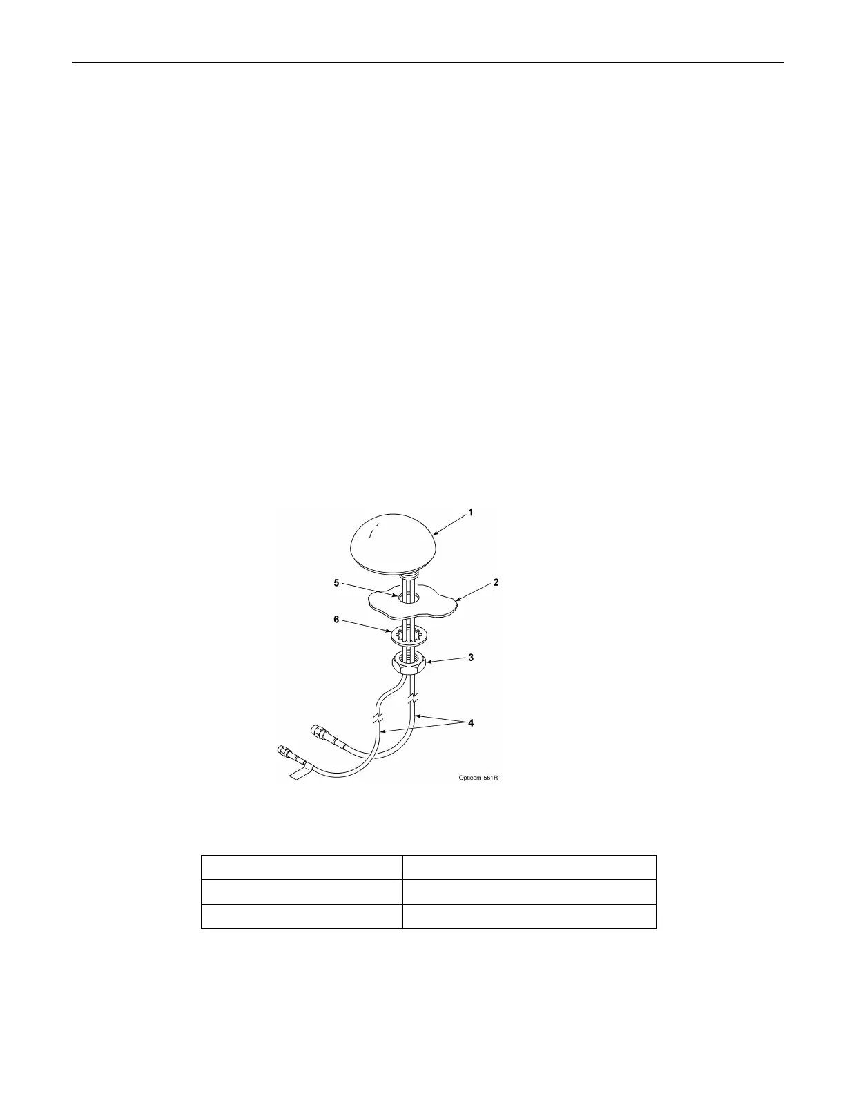
Figure 3-7. Mounting Model 1050 Radio/GPS Antenna on Cabinet Roof
1. Radio/GPS antenna 4. Radio and GPS antenna cables
2. Traffic cabinet roof 5. 5/8 to 3/4-inch mounting hole
3. Antenna nut 6. Antenna lock washer