Intersection Equipment Installation Instructions
31
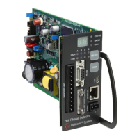
9.1 Auxiliary Interface Panel Installation
Notes:
• See tables 9-1, 9-2, and 9-3 for a description of the connectors and terminal strips
• Wire gauges from 22 to 16 AWG may be used to connect from the auxiliary interface panel to the
traffic control cabinet wiring.
• Any given installation may not require the use of all auxiliary interface panel terminals.
• Leave connector cover in place on J4 if the J4 connector is not being used.
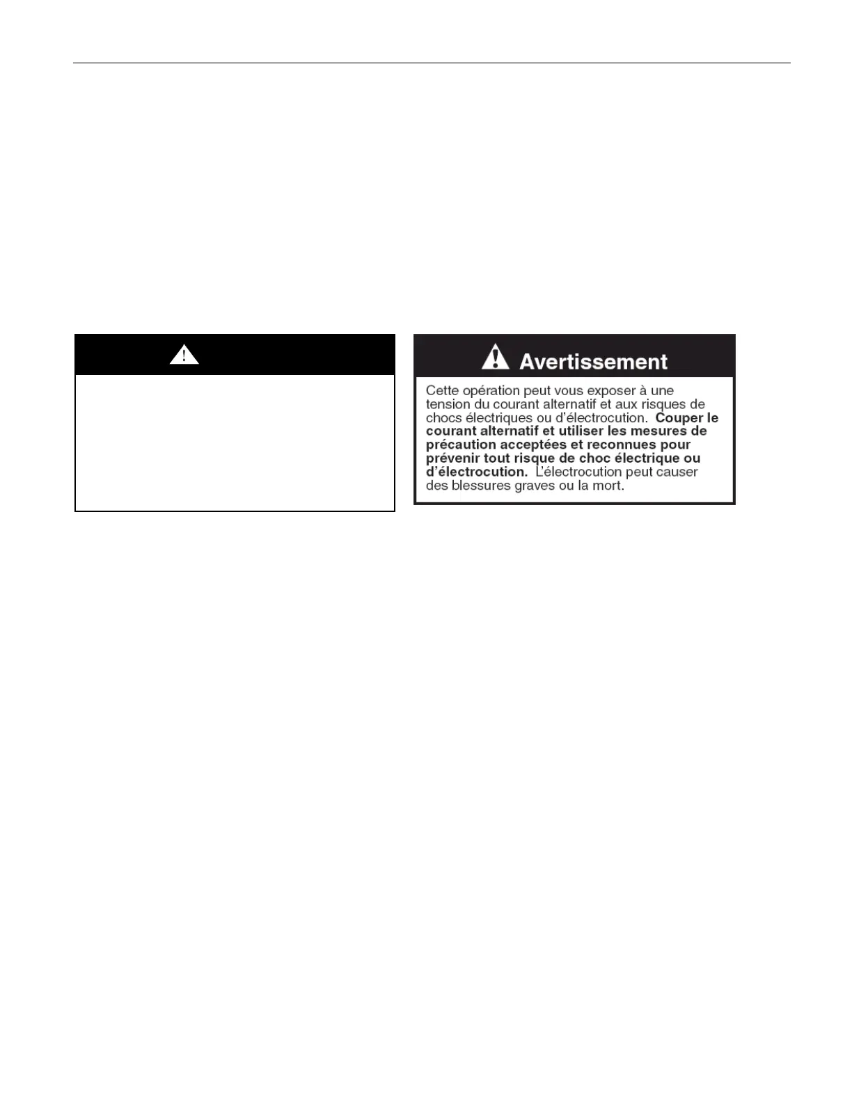
WARNING
This procedure may expose you to AC
voltage and the risk of electric shock or
electrocution. Turn off the AC mains and
use accepted and recognized safety
precautions to avoid exposure to the risk of
electric shock or electrocution. Electric
shock may cause severe injury or death.
1. Determine a suitable location for the auxiliary interface panel in the traffic control cabinet. See Figure 9-
2.
2. Use the mounting plate as a template and mark where you want to drill holes or use spring nuts to
attach to the cabinet mounting channel.
3. Drill the holes and fasten the panel to the interior wall with user-supplied fasteners or use spring nuts to
attach to the cabinet mounting channel.
4. Connect one end of the auxiliary interface panel cable to the connector labeled AIP on the front
panel of the phase selector and the other end to J2 on the auxiliary interface panel. See Figure 9-2.