Intersection Equipment Installation Instructions
8
Intersection Equipment Details
The Opticom™ GPS System intersection equipment has two styles of Radio/GPS units available.
The first is the Model 1010, which is a compact, weather-resistant, Radio/GPS unit containing a GPS receiver
with antenna and a 2.4 GHz transceiver with antenna. This model is typically mounted on a traffic pole near
the traffic cabinet.
The second is the Model 1012 Radio/GPS unit, which contains a GPS receiver, a 2.4 GHz transceiver and a
separate Radio/GPS antenna. This model is mounted in the traffic cabinet with the antenna mounted on the
roof of the cabinet.
Both models of the Radio/GPS unit are connected to a phase selector via an 11-conductor radio/GPS cable.
The phase selector can be installed directly into an input file of a traffic controller equipped with priority
phase selection software. The phase selector can also be installed directly into virtually any other traffic
controller equipped with priority phase selection inputs and related software.
When input file space is not available in the traffic cabinet, a card rack is required.
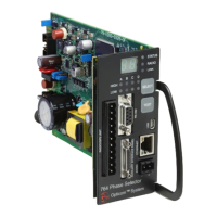
The phase selector processes the signal from the radio/GPS unit and activates outputs which are connected
to the preemption inputs on the traffic controller. There are four channel outputs accessible on the rear
connector of the phase selector and up to 12 additional channel outputs accessible on the front of the phase
selector.
Each channel output delivers a constant output for high priority activation, and a pulsed output for low
priority activation. A high priority signal received on a channel will override any low priority activation. In
certain modes of operation, outputs may be activated that are dependent on the state of the requesting
vehicle’s turn signal. Another mode provides separate outputs for high priority and low priority. The use of
an auxiliary interface panel is required to access these additional modes and outputs.
Figure 2-1 shows the intersection components including the phase selector, card rack, input file, auxiliary
interface panel, and the wiring harnesses and cables. The 9-pin harness connects the card rack to the traffic
controller. Various communication ports are available to connect the phase selector to a PC or to remote
communication equipment. Additional communication connections are available on the auxiliary interface
panel. The auxiliary interface panel cable connects the phase selector to the auxiliary interface panel. The
radio/GPS cable connects the phase selector to the intersection radio/GPS unit.
NOTE: Illustrations and connections to the traffic controller may not be exactly as shown or described in
this manual. Refer to the controller wiring diagram for correct terminal connections.