Intersection Equipment Installation Instructions
25
1. Place the card rack at the desired location in the controller cabinet.
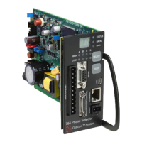
2. Install the phase selector into the card rack making sure it is fully seated. See Figure 5-19.
3. Route the 9-pin harness wires to their terminals.
4. Strip 1/4-inch (6 mm) of insulation from each wire to be used.
5. Install a spade lug on each wire and connect it to the appropriate terminal. See Figure 5-18 and Table
5-6.
6. Locate the controller terminals for AC+, AC–, chassis ground, and connect these wires.
7. Power input range: 89 to 135 VAC, 60 Hz.
8. Connect the AC wires after the circuit breaker and surge suppression devices.
9. Connect the logic ground wire to a logic ground/logic common terminal.
10. Connect the priority output wires to the appropriate preempt inputs.
11. Connect plug P1 of the 9-pin harness to connector J1 on the card rack front panel.
Color
Number
Function
Black 1 115 VAC (AC+)
White 2 AC return (AC–)
Green 3 Chassis ground
4 Not used
Gray/White 5 Rear output 1
Blue/White 6 Rear output 2
Violet/White 7 Rear output 3
Brown/White 8 Rear output 4
Gray/Black 9 Logic ground
Table 6-1 9-Pin Harness Wiring 760 and 1040 card racks