Intersection Equipment Installation Instructions
19
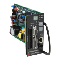
Figure 3-9. Radio/GPS Cable Connector Pin Configuration
Pin Wire Color Function
1 Yellow Radio transmit (+)
2 Yellow Black Radio transmit (–)
4 Blue Radio receive (+)
5 Blue White Radio receive (–)
7 Orange Radio clock (+)
8 Orange Green Radio clock (–)
9 Brown GPS power
11 Brown White Common
12 Violet White Common
13 Bare Shield drain wire
15 Violet Radio power
Table 3-1. Radio/GPS Cable Connector Pin Index
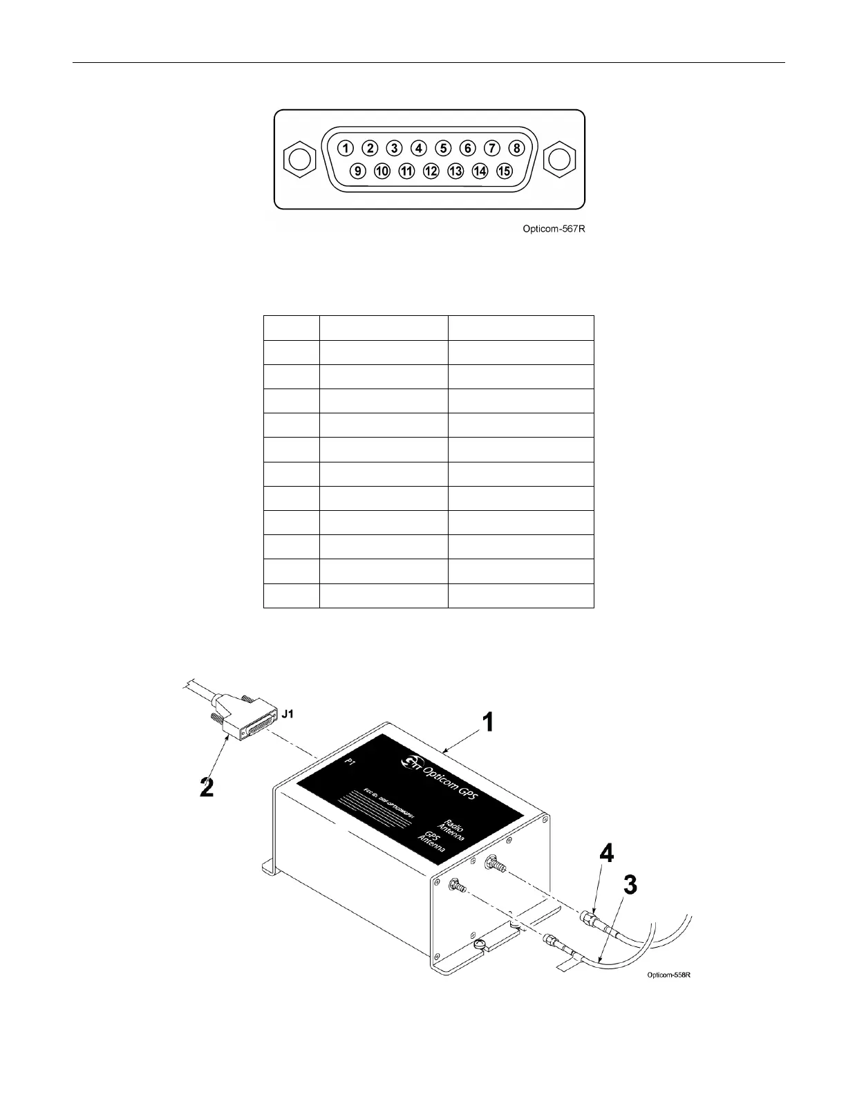
Figure 3-10. Radio/GPS Installation Cable