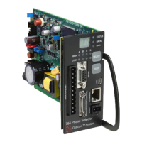
Intersection Equipment Installation Instructions
37
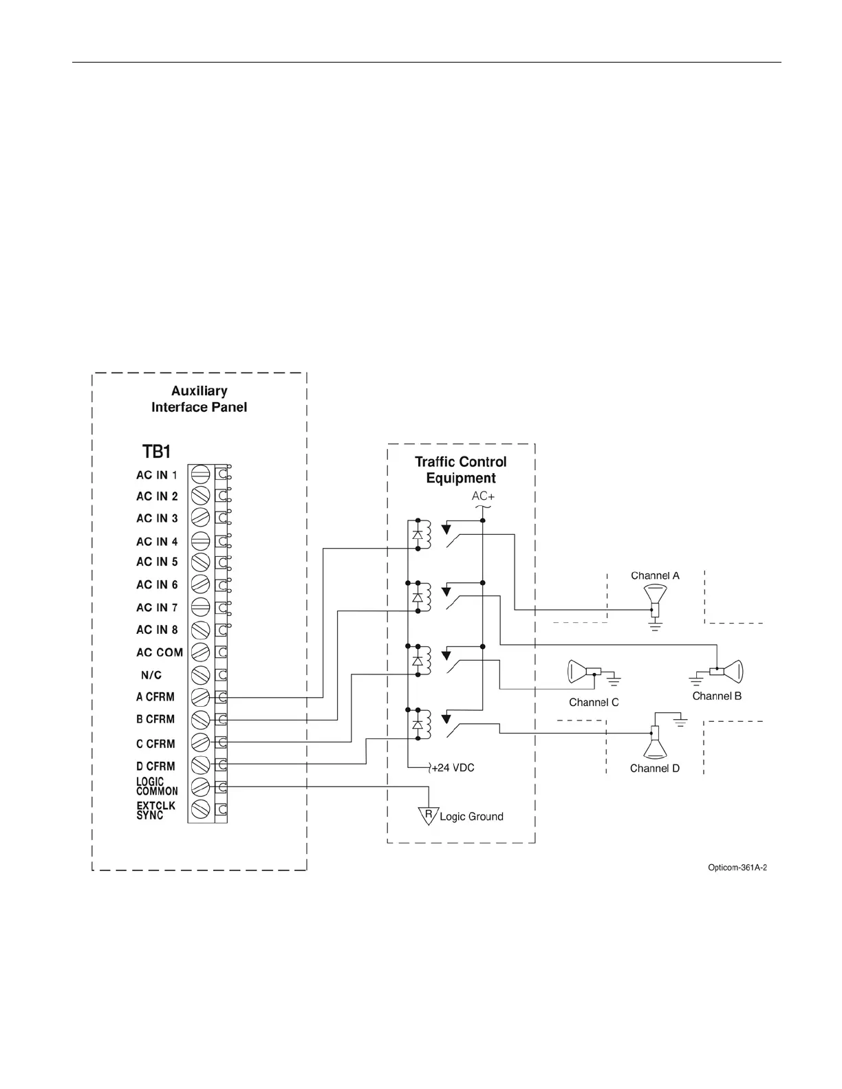
9. Connect a wire to one of the LOGIC COMMON terminals of the auxiliary interface panel. Install a spade
lug on the other end of the wire and connect it to the traffic controller logic ground. See Figure 9-4.
10. Connect a +24 VDC power source to each of the four confirmation light relays as shown in Figure 9-4.
11. Complete the configuration light interface wiring and field wiring as shown in Figure 9-4.
12. Verify that your wiring is correct, and the connections are tight.
13. Select the appropriate confirmation light pattern using the On-site software. See the On-site help file for
details.
Figure 9-4. Confirmation Light Wiring with Electromechanical Relay Interface